A5E01070504A-02 Last update: 01 April 2011
Order No.: 3ZX3012-0US50-0AY0
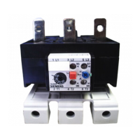
Overload Relay with
Phase Loss Sensitivity
3US50, 3US55
DIN VDE 0660 part 102, IEC 60947-4-1,
Q/320500 SMS 011, GB14048.4
Operating Instructions
English
Fig. Ia: 3US50: For mounting on contactors 3TS29 / 30 / 31 / 32,
Individual mounting possible with assembly kit 3US1950-8.
Fig. Ib: 3US55: For mounting on contactors 3TF33 / 34,
Individual mounting possible with assembly kit 3US1955-8.
Dimension drawings (dimensions in mm): Fig. II
1)
Keep distance to earthed parts.
2)
Where 3TS contactors are screwed or snapped onto a standard mounting
rail (35 x 7.5 mm rail to DIN EN 50 022) fixed onto a non-insulating
surface, insulation should be provided between the relay and the
non-insulating surface so as to obtain the air gap specified in UL 508.
3)
For snap-on fastening on standard sectional rail, DIN EN 50 022.
Dimension for square OFF button (stroke 3 mm).
Dimension for round RESET button (stroke 2.5 mm) dimension minus
2.5 mm.
4)
Permissible installed positions: Fig. III
a Overload relay with contactor
b Overload relay for individual mounting
Do not subject to sudden shocks or long-term vibrations.
Equipment circuit diagram: Fig. V
Permissible cable cross-sections: Fig. IV
In the case of several single-phase loads, the three main circuits must be
connected in series.
Instructions: Fig. VI
➀ Set the scale to the rated current of load.
➁ Reset button (blue)
Push this button before commissioning and after tripping to make relay
ready for operation.
In the as-delivered condition, the auxiliary contact is set to H = Manual
resetting.
To change from H = Manual to A = Automatic, press and turn the button
counter-clockwise from H to A.
➂ Test button (red)
When this button is actuated, the NC contact opens and the NO contact
closes, i.e. a test function for NC and NO contacts (simulation of overload
tripping).
In the "Manual" position, the relay is reset when the blue button is
pressed.
In the „Automatic“ position, the relay is reset automatically when the red
button is released.
➃ TRIPPED indication (green)
In the H setting, a green pin protrudes from the front plate to indicate the
TRIPPED condition. In the A setting, this condition is not indicated.
➄ Terminal for contactor coil, A2.
Tripping characteristics: Fig. VII
The characteristics conform to VDE 0165, VDE 0170 / 0171 for
machines with type of protection E Ex e.
Tripping times are shown for a three-phase load from the cold state
(ambient temperature +20 °C). In the case of hot relays, preloaded with
1xI
E
, the tripping times decrease by approx. 25 %.
I
E
: Current setting
t
A
: tripping time in seconds (+ 20 %)
➀ Setting range (I = lowest value of current setting I
E
, II = highest value of
current setting I
E
)
➁ Type designation / Order No.
Main circuit
Auxiliary circuit
Rated operational current:
Rated insulation voltage:
Short-circuit protection:
Operating conditions at ambient temperatures > 55 °C
At ambient temperatures > 55 °C, you must
1. Reduce the current loading for the overload relay
2. Upwardly correct the setting current to prevent tripping at motor rated
current.
Correction factors:
Calculation example:
Motor rated current: 10 A
Ambient temperature: 70 °C
Overload relay fitted: 8 to 12.5 A
1st Step: Determine the permissible current loading:
Max. current loading: 12.5 A x 0.82 = 10.25 A
Loading with motor rated current 10 A at 70 °C ambient temperature is per-
missible.
2nd Step: Calculate the setting current:
Motor rated current: 10 A
Setting current correction: 10 A x 1.1 = 11 A
You must set the overload relay to 11 A.
For further information and accessories, see Catalog IC15.
Read and understand these instructions before installing,
operating, or maintaining the equipment.
DANGER
Hazardous voltage.
Will cause death or serious injury.
Turn off and lock out all power supplying this device before
working on this device.
CAUTION
Reliable functioning of the equipment is only ensured with
certified components.
Mounting
Connection
Commissioning
Technical data
Rated insulation voltage 690 V
Rated operational current 3US50: 0.1 ... 18 A
3US55: 6.3 ... 32 A
Permissible ambient air temperature -25 °C .... +55 °C
Degree of protection see nameplate
AC-15 / U
e
V 24 60 125 230 400 500
690
AC-15 / I
e
A 2 1.5 1.25 1.15 1.1 1
0.8
DC-13 / U
e
V 24 60 110 220
DC-13 / I
e
A20.50.30.2
400 V
different potential
690 V
same potential
NH, NEOZED or DIAZED fuses 6 A gG or10 A fast
Miniature circuit-breaker 3 A (C-characteristic)
Ambient
temperature
Perm. Current loading
referred to end-of-scale value
Setting current
correction
55 °C 1 1
60 °C 0.94 1.08
65 °C 0.88 1.09
70 °C 0.82 1.1