4
3. Trip indicator
3.1 Equipping the tripping board
- Assemble the indicator
3. Ausgelöstmeldung
3.1 Auslöserplatte bestücken
- Meldung montieren
9
10
Klemme X4
Terminal X4
Fig. 7 Meldung anschließen
Connecting indicator
Fig. 6 Montierte Gesamtdarstellung
Assembled general view
3.2 Anschließen der Meldung
– Die Leitungen der Meldung durch die Leitungs-
bohrung 10 ziehen und durch den Leitungskanal 9 zur
Klemme X4 führen. Leitungen an X 4.9 und X 4.10
anschließen
3.2 Connecting the indicator
– Enter the conductors of the indicator through cable
hole 10 and run them through duct 9 to terminal X4.
Connect the conductors to X4.9 and X4.10
1
7
2
3
5
4
8
6
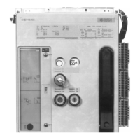
Fig. 5 Meldung montieren
Assembling the indicator
Schraube/Screw M3 x 5
Scheibe/Washer 3.2
Zahnscheibe/Toothed washer 3.2
Zylinderschraube
AM 3x25-4
Cylinder head screw
Mikroschalter/
Micro switch
Abstandsrohr
6 x 1x 8
Spacer tube
Sechskantmutter
M3
Hexagon nut
Blech/Plate
F7
Magnet/Solenoid
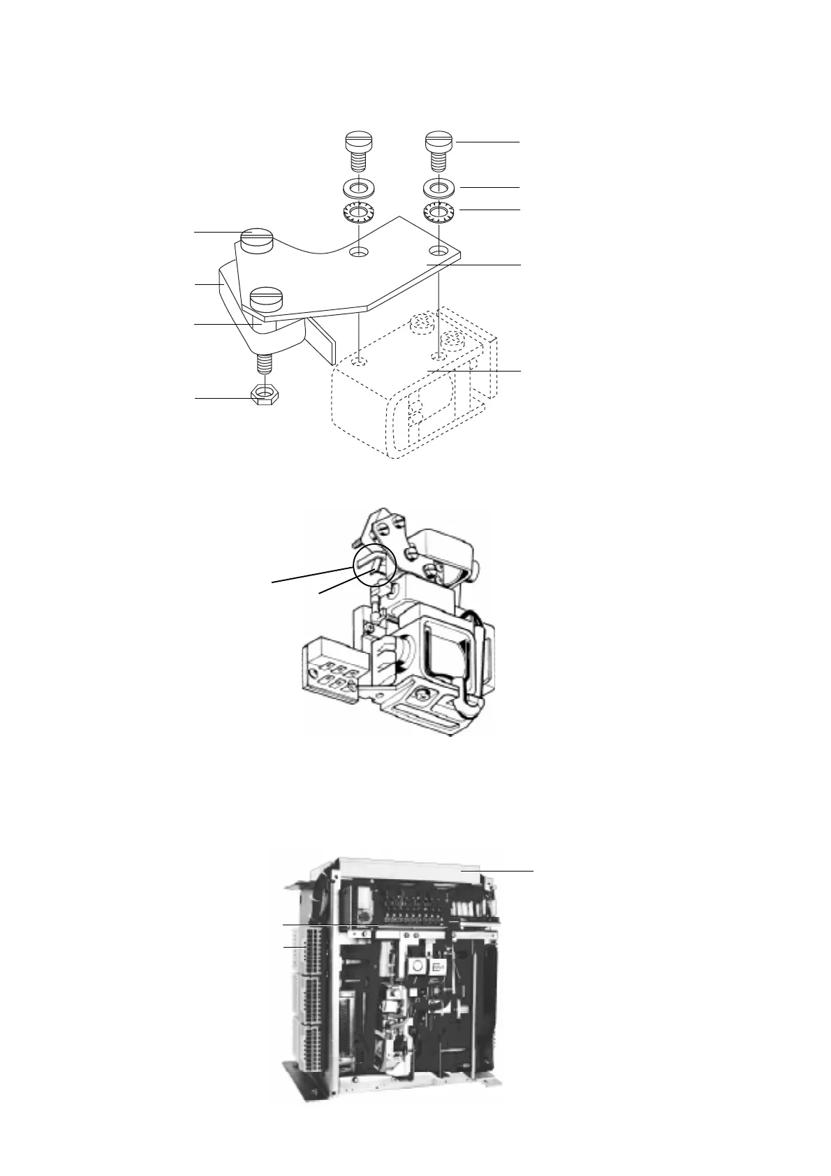
Hinweis:
Auf genauen Einbau im Bereich X
achten! (Fig. 6)
Der Betätigungshebel (11) des
Mikroschalters (4) muß entspre-
chend, wie in Fig. 6 dargestellt, im
Mitnehmer liegen.
Note:
Take special care when assembling in
region X. (Fig. 6)
The operating lever (11) of the micro
switch (4) must be positioned in the
driver as shown in Fig. 6
X
11
 Loading...


