Do you have a question about the Siemens 6DR55 Series and is the answer not in the manual?
Provides an overview of the product's safe and reliable operation.
Explains safety notice symbols (DANGER, WARNING, CAUTION) and their meanings.
Defines qualified personnel and their responsibilities for safe operation and maintenance.
Specifies the intended applications and safe usage of the product.
Lists available technical documentation and how to access it online.
Clarifies that manual content does not modify warranty terms.
Instructions for checking delivery completeness and condition upon receipt.
Mentions adherence to European standards and country-specific regulations.
Describes the positioner's function, communication interface, and applications.
Introduces PROFIBUS PA as an open communication system for automation.
Provides a general overview of the positioner's control system and operation.
Explains the information found on the positioner's rating plate.
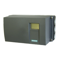
Identifies and describes the main physical components of the positioner.
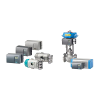
Details how the positioner interacts with the actuator and control system.
Describes the positioner's condition as delivered from the factory.
Lists and describes available optional modules for the positioner.
Guides on identifying the positioner using its order number and type key.
Provides essential physical dimensions for installation planning.
Outlines the general assembly steps and safety precautions for the positioner.
Provides instructions and safety warnings for connecting the positioner electrically.
Details pneumatic connection requirements, air quality, and safety measures.
Explains the process of setting up and initializing the positioner for operation.
Describes how to transfer initialization data when replacing a positioner.
Explains the liquid crystal display and its segmentation.
Details the function and operation of the positioner's input keys.
Outlines the five available operating modes of the positioner.
Lists and describes all configurable parameters for the positioner.
Explains how to access and interpret diagnostic information.
Explains various status and error messages displayed by the unit.
Guides on tuning parameters for optimal control quality.
Provides a troubleshooting guide for common faults and their corrective actions.
Explains how the positioner integrates into a PROFIBUS DP/PA system.
Details the use of acyclic data for parameter transfer and diagnostics.
Describes cyclic data transfer for process automation.
Explains the exchange of cyclic data between the positioner and the PROFIBUS.
Details diagnostic data reporting according to PROFIBUS DP standards.
Explains how to interpret condensed status information for diagnosis.
Provides detailed technical specifications for the SIPART PS2 positioner.
Lists technical specifications for various optional modules.
Provides technical specifications for accessory modules like mounting kits.
Provides selection and ordering data for configuring the positioner.
Lists the order numbers for available option modules.
Lists the order numbers for various accessories.
Provides a list of spare parts with their order numbers.
Lists relevant literature and catalogs for further information.
Mentions that certificates are enclosed separately.
| Brand | Siemens |
|---|---|
| Model | 6DR55 Series |
| Category | Valve Positioners |
| Language | English |