Installation, connection, commissioning, removal
5.3 Installing and connecting up
CP 343-1 Lean
Equipment Manual, 01/2023, C79000−G8976−C198−09
41
Connecting interface X1 to Industrial Ethernet
1. Connect the CP to Industrial Ethernet via one of the RJ45 jacks.
2. Where necessary, connect another component to the remaining free RJ45 jack.
- effects on the connectors
For small local area networks or for attaching several Ethernet devices, a 2
port switch has
been integrated on the PROFINET interface of the CP.
With the autocrossing mechanism integrated in the switch, i
t is possible to use a standard
cable to connect the PG/PC. A crossover cable is not necessary.
Please note the following points:
Manual configuration
If a port is set to manual configuration and autonegotiation is disabled, the
autocrossing mechanism is also disabled for this port. Which cable you need to use
depends on the partner device (network component or end device).
In the factory, the ports are set for automatic configuration.
For more information, refer to section Network settings (Page 47)
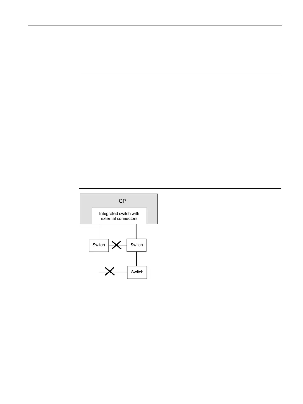
Connecting switches
If you connect further switches, make sure that no ring is formed in the network.
Figure 5-2 Connecting switches
With an MRP configuration, keep to the setup guidelines for MRP.
You will find examples of network attachments in the general Part A of this manual, see
/1/ (Page 73).
 Loading...


