Do you have a question about the Siemens RWF55.6 and is the answer not in the manual?
Important safety information, warning symbols, and personnel qualifications.
Step-by-step guide for securely mounting the controller in a panel.
Detailed mapping of controller terminals to functions and circuits.
Defines system response dynamics to control deviation for switching to higher output.
Controller behavior when starting a system after a prolonged shutdown period.
Function to protect equipment from rapid temperature changes.
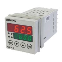
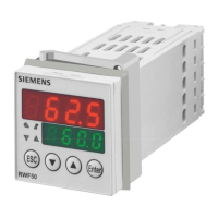
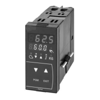
Explanation of the controller's front panel indicators and operational buttons.
Procedure for manually controlling the modulating burner operation.
Procedure for manually controlling the 2-stage burner operation.
Steps to initiate the automatic controller parameter tuning process.
Configuration of controller type, operating action, and setpoint limits.
Configuration of thermal shock protection and alarm functions.
| Display | LCD |
|---|---|
| Protection Category | IP30 |
| Power Supply | AC 24 V |
| Temperature Range | 0 °C to +50 °C |
| Mounting Type | Wall mounting |
| Digital Outputs | 2 |
| Analog Inputs | 1 |
| Weight | 300 g |
| Ambient Temperature Range | -10…50 °C |
| Digital Inputs | 2 |




 Loading...