Do you have a question about the Siemens RWF40 Series and is the answer not in the manual?
Important notes for users before starting up the controller and handling ESD.
Details the use, control, and options of the RWF40... controller, including dimensions and displays.
Explains warning symbols, notification symbols, and button presentation conventions used in the manual.
Explains the type designation, its location, and lists different unit types with their descriptions.
Specifies requirements for the installation site, including freedom from vibrations, dust, and corrosive media.
Provides detailed dimensions of the controller and the required panel cutout according to DIN 43700.
Outlines minimum spacing requirements when mounting multiple controllers side-by-side or one above another.
Details the procedure for mounting the controller in a panel cutout, including seal placement and fixing elements.
Covers safety regulations, fusing, interference suppression, and incorrect use concerning electrical connections.
Illustrates the controller's inputs, outputs, operating voltage, and serial interface connections schematically.
Details the terminal assignments for outputs, including contact protection and connection diagrams.
Illustrates maximum potential differences between function modules and shows maximum insulation voltages.
Explains low-fire operation and the thermostat function, including switching differentials.
Describes high-fire operation, including its use in modulating or two-stage burner control.
Details the modulating burner operation with a 3-position output, showing its behavior in different stages.
Explains modulating burner operation using a modulating output, including the positioning signal.
Describes two-stage burner operation with a 3-position controller, detailing its actions at different thresholds.
Explains two-stage burner operation with a modulating output, triggered by binary signals and thresholds.
Covers safety shutdown procedures, triggered by sensor failure or external setpoint issues.
Introduces pre-selected setpoints that can be shifted via analog or binary signals for weather influence or external changes.
Details setpoint changeover between SP1/SP2 and analog setpoint shift based on configuration.
Explains how to change setpoint SP1 using buttons, an outside sensor, or an external setpoint.
Describes setpoint SP1 with analog or binary shift options, integrating weather-dependent shifts.
Outlines the function of an external setpoint combined with a binary setpoint shift.
Details how a weather-dependent setpoint shift is implemented using an outside sensor and heating curves.
Explains how the heating curve slope (H) adjusts the setpoint based on outside temperature.
Defines the response threshold 'Q' which determines when the system switches to high-fire operation.
Describes how the controller handles cold starts, initiating immediate high-fire operation for faster response.
Explains how to access different operational levels (Basic, User, Parameter, Configuration) using the PGM button.
Describes the initial display after power-on, showing actual value and setpoint, and enabling access to other levels.
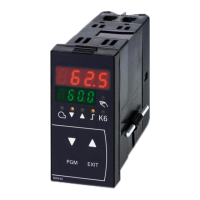
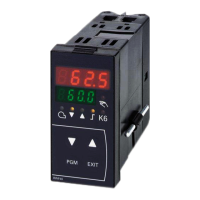
Identifies the function of the displays (actual value, setpoint) and control buttons (PGM, EXIT, ▲, ▼).
Describes how to access and modify setpoints (SP1, SP2, dSP) and view analog inputs.
Provides step-by-step instructions for altering setpoints SP1, SP2, and dSP in the user level.
Details manual operation for modulating burners, covering 3-position and modulating controllers.
Explains manual operation for two-stage burners, describing actions for relay 2, 3, and analog output.
Instructs on how to initiate and cancel the self-setting function and accept its parameters.
Guides on how to display the software version and the unit of the actual value using button combinations.
Explains how to access and alter parameters for adapting the controller to the system.
Details the process of entering and altering parameter values using the controller buttons.
Describes the configuration level, used for commissioning settings like measured value acquisition and controller type.
Explains how to select and alter the configuration code in the configuration level.
Details key parameters like limit values, differentials, PID settings, thresholds, and curve slopes for controller adaptation.
Lists the possible configurations for Analog Inputs 1 and 2, including sensor types and signal ranges.
Specifies the configuration options for Analog Input 3, related to outside temperature sensors.
Details the configuration options for binary input D2, such as setpoint shift or changeover.
Covers configuration of limit comparator functions, controller type, setpoint source, and locking options.
Explains the 'Window function' (Ik1) for relay K6, detailing its behavior with measured value rising/falling.
Describes 'Function Ik2' which is similar to Ik1 but with an inverted switching function for relay K6.
Details 'Function Ik3' (Lower limit signaling) for relay K6, explaining its behavior based on measured value relative to setpoint and limit value.
Explains 'Function Ik4' as an inverted version of Ik3 for relay K6's switching behavior.
Describes 'Function Ik5' (Upper limit signaling) for relay K6, defining its behavior based on measured value relative to setpoint and limit value.
Details 'Function Ik6' as an inverted version of Ik5 for relay K6's switching behavior.
Explains 'Function Ik7' where switching point depends only on limit value 'AL', not setpoint.
Describes 'Function Ik8' as an inverted version of Ik7 for relay K6's switching behavior.
Covers configuration of unit address, decimal places, units, and out-of-range signal settings.
Explains scaling of standard signal ranges for Analog Inputs 1 and 2.
Defines parameters 'SPL' and 'SPH' for setting the lower and upper limits of the setpoint range.
Details 'OFF1', 'OFF2', and 'OFF3' for correcting actual values of Analog Inputs 1, 2, and 3.
Describes 'dF1' for setting the time constant of the 2nd order digital filter for Analog Input 1.
Explains the 'tunE' self-setting function in high-fire, modulating burner mode, and its procedures.
Lists the conditions required for self-setting, including high-fire operation and thermostat activation.
Guides on checking controller parameters after self-setting by analyzing startup sequences.
Addresses issues where numbers flash on the display, indicating incorrect measured value acquisition.
Provides technical specifications for Analog Input 1 (actual value) covering resistance thermometers, thermocouples, and standard signals.
Details specifications for Analog Input 1, including measured value ranges and line compensation.
Details technical specifications for Analog Input 2, including potentiometers and standard signals for setpoint functions.
Specifies technical data for Analog Input 3, focusing on resistance thermometers for outside temperature.
Describes the function of binary input D1 for operating mode changeover between modulating and 2-stage burners.
Outlines the potential functions of binary input D2, such as setpoint shift or changeover, based on configuration.
Details the specifications for the controller's outputs, including relay outputs and optional modulating analog output.
Provides contact rating, life, and protection details for Output 1, which releases the burner.
Details specifications for Outputs 2 and 3, used for 3-position output to control regulating units.
Provides details for Output 4, used as a limit comparator with relay output.
Specifies technical data for the optional Output 5, a continuous modulating output.
Gives specifications for the transducer supply, a DC 24 V output.
Details technical specifications for the optional RS-485 serial interface, including baud rate and protocol.
Covers general specifications like weight, data backup, operating voltage, power consumption, and electrical connection.
Lists the measured value accuracy for different transducer types and ambient temperature errors.
Explains how probe breaks and short-circuits are detected for various transducers.
Specifies permissible ambient and storage temperatures, relative humidity, and degree of protection.
Lists process data parameters like setpoints, digital setpoint shift, and outside temperature.
Presents parameters available in the parameter level, including limit comparators, PID settings, and thresholds.
Lists parameters for the configuration level, such as input/output settings and scaling values.
| Product Type | Controller |
|---|---|
| Display | LCD |
| Output current | 0.5 A |
| Series | RWF40 |
| Input voltage | 24 V DC |
| Operating temperature | 0°C to +55°C |


 Loading...