30/56 CC1B7865E February 10, 2000 Landis & Staefa Division
6. Operation
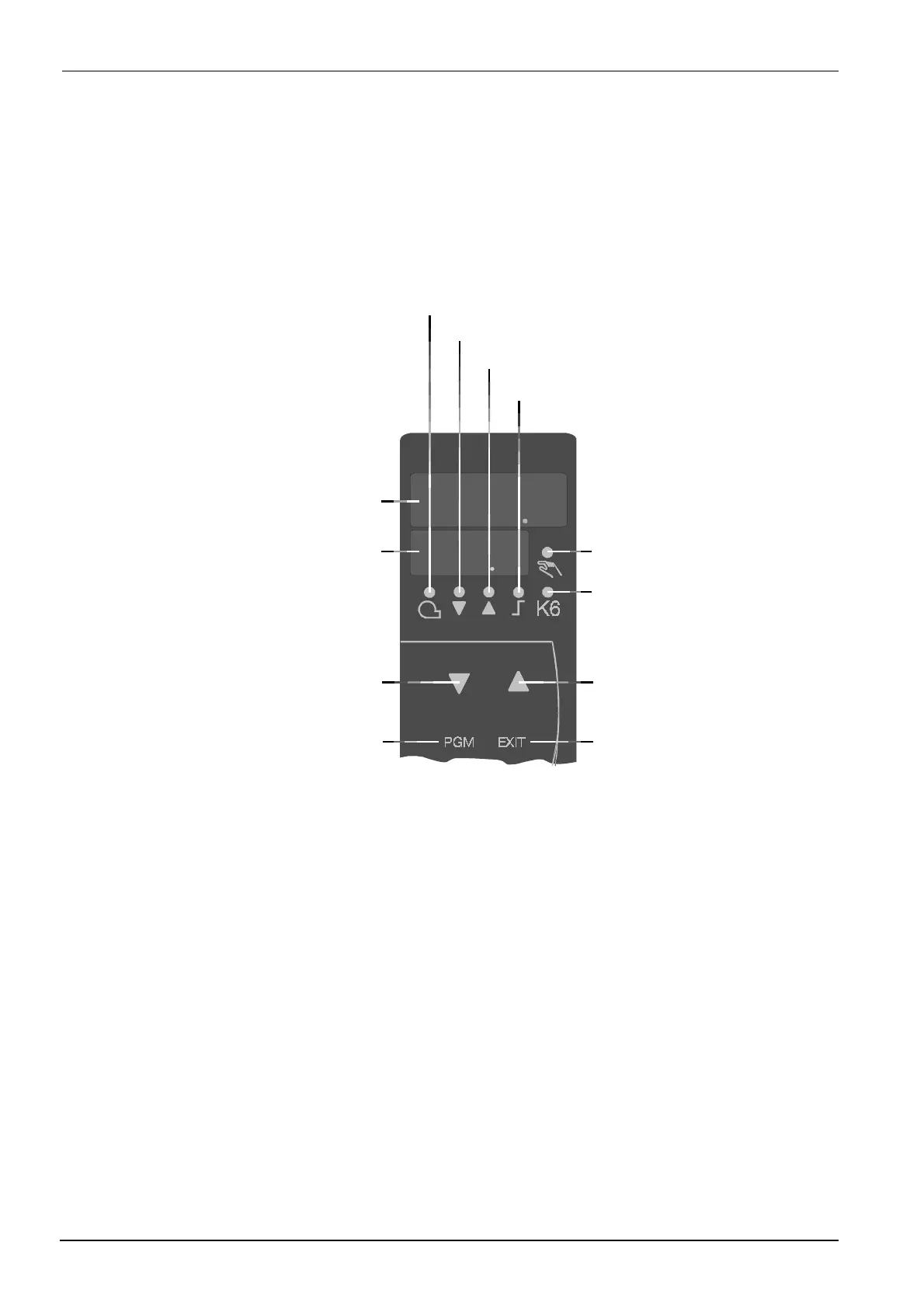
The diagram shows the RWF40... after switching on power. This condition is called the
basic display. The actual value and the currently active setpoint are shown here. Manual
operation, self-setting, the user, parameter and configuration levels can be activated
from here.
503
639
Limit comparator
Increase value
EXIT button
Manual operation
2-stage operation
PGM button
Regulating unit OPEN / 2nd stage
Regulating unit CLOSE / 1st stage
Release of burner
Actual value
display (red)
Setpoint display
(green)
7865p02e/0200
Decrease value
6.1 Basic display
6.1.1 Meaning of the display and buttons

 Loading...


