Landis & Staefa Division CC1B7865E February 10, 2000 17/56
4. Electrical connections
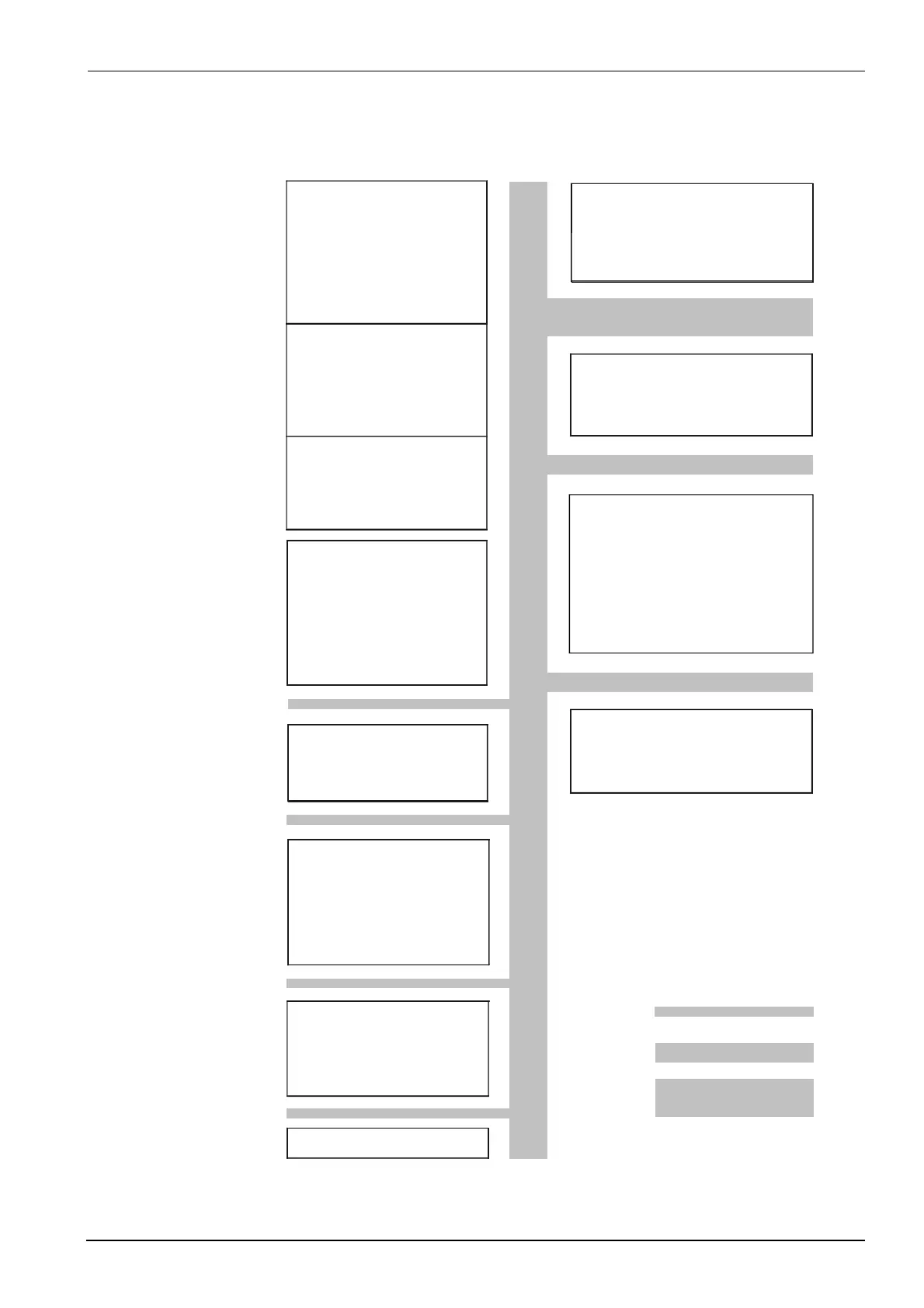
The diagram shows the maximum potential differences that may exist between the
function modules in the controller.
Max. insulation voltages:
DC 50 V
AC 400 V
AC 4000 V
7865f07e/1299
3 analog inputs
Input 1:
Actual value
for Pt100, Ni100,
Pt1000, Ni1000
thermocouples or
standard signals
Ω
Input 2:
External setpoint,
setpoint shift
for resistance 0...1 k ,
or standard signals
Input 3:
Outside temperature
for Pt1000, Ni1000
2 binary inputs
for potential-free contacts
D1:
operating mode
changeover
D2:
setpoint shift /
changeover
Transducer supply
DC 24 V , 30 mA
(short-circuit proof)
Modulating output
(optional)
Output 5:
Modulating output,
DC 0...10 V,
DC 0...20 mA, 4...20 mA
Serial interface
RS-485 (optional)
MOD bus protocol
baud rate 9600
Technical earth TE
Limit comparator
Output 4:
- Relay (N.O. contact)
Release of burner
L1, N:
Output 1:
- Relay (N.O. contact)
3-position output
L1, N:
Output 2:
- Relay (reg. unit opens)
Output 3:
- Relay (reg. unit closes)
±
Operating voltage
L1, N:
AC 100...240 V 10 %,
48...63 Hz
4.4 Galvanic separation

 Loading...


