Landis & Staefa Division CC1B7865E February 10, 2000 51/56
11. Technical data
For resistance thermometers, thermocouples or standard signals with 2
nd
order digital
filter (configurable).
In 2-wire or 3-wire circuit:
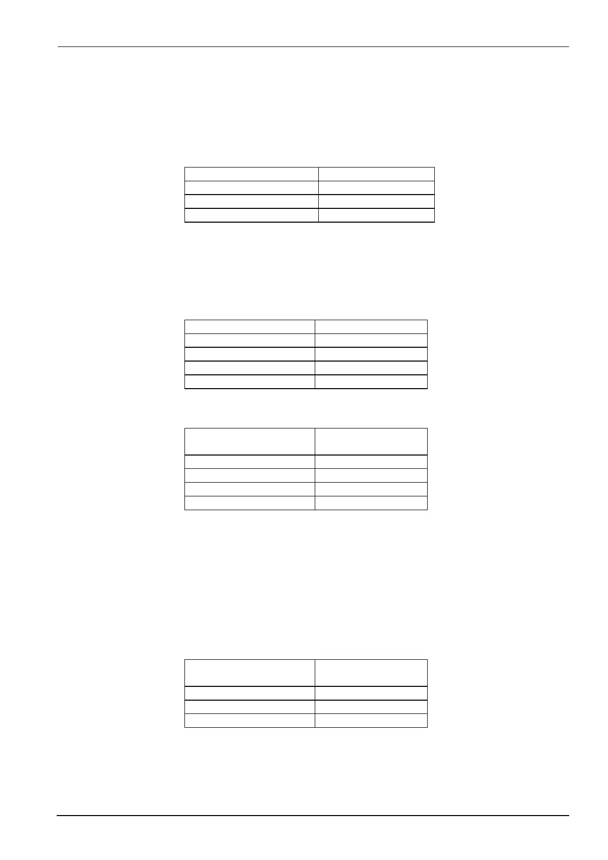
Type Measured value range
Pt100, Pt1000 -200...+850 °C
Ni100, Ni1000 DIN 43760 -60...+250 °C
Ni1000 from Landis & Staefa -50...+160 °C
Line resistance
: < 30
Ω
Line compensation
Not required for a 3-wire circuit.
When using a resistance thermometer in a 2-wire circuit, line compensation can only be
made by means of the offset correction.
Type Measured value range
Fe-CuNi «J» -200...+1000 °C
NiCr-Ni «K» -200...+1372 °C
Cu-CuNi «T» -200...+400 °C
NiCrSi-NiSi «N» -100...+1300 °C
Cold-junction temperature
: internal
Signal Internal resistance Ri
Voltage drop
∆
∆∆
∆
Ue
DC 0...10 V R
i
= 2 M
Ω
DC 0...1 V R
i
= 2 M
Ω
DC 0...20 mA
∆
U
e
= < 1 V
DC 4...20 mA
∆
U
e
= < 1 V
Sampling time: 210 ms
Resistance measured value 0…1 k
Ω
standard signals without linearization.
With 2-wire circuit
R = 0…1 k
Ω
Signal Internal resistance Ri
Voltage drop
∆
∆∆
∆
Ue
DC 0...10 V R
i
= 2 M
Ω
DC 0...20 mA
∆
U
e
= 1 V
DC 4...20 mA
∆
U
e
= 1 V
Sampling time: 630 ms
11.1 Inputs
11.1.1 Analog input 1 (actual value)
Resistance thermometers
Thermocouples
Standard signals
11.1.2 Analog input 2 (external setpoint, setpoint shift)
Potentiometer
Standard signals

 Loading...


