38/56 CC1B7865E February 10, 2000 Landis & Staefa Division
8. Configuration
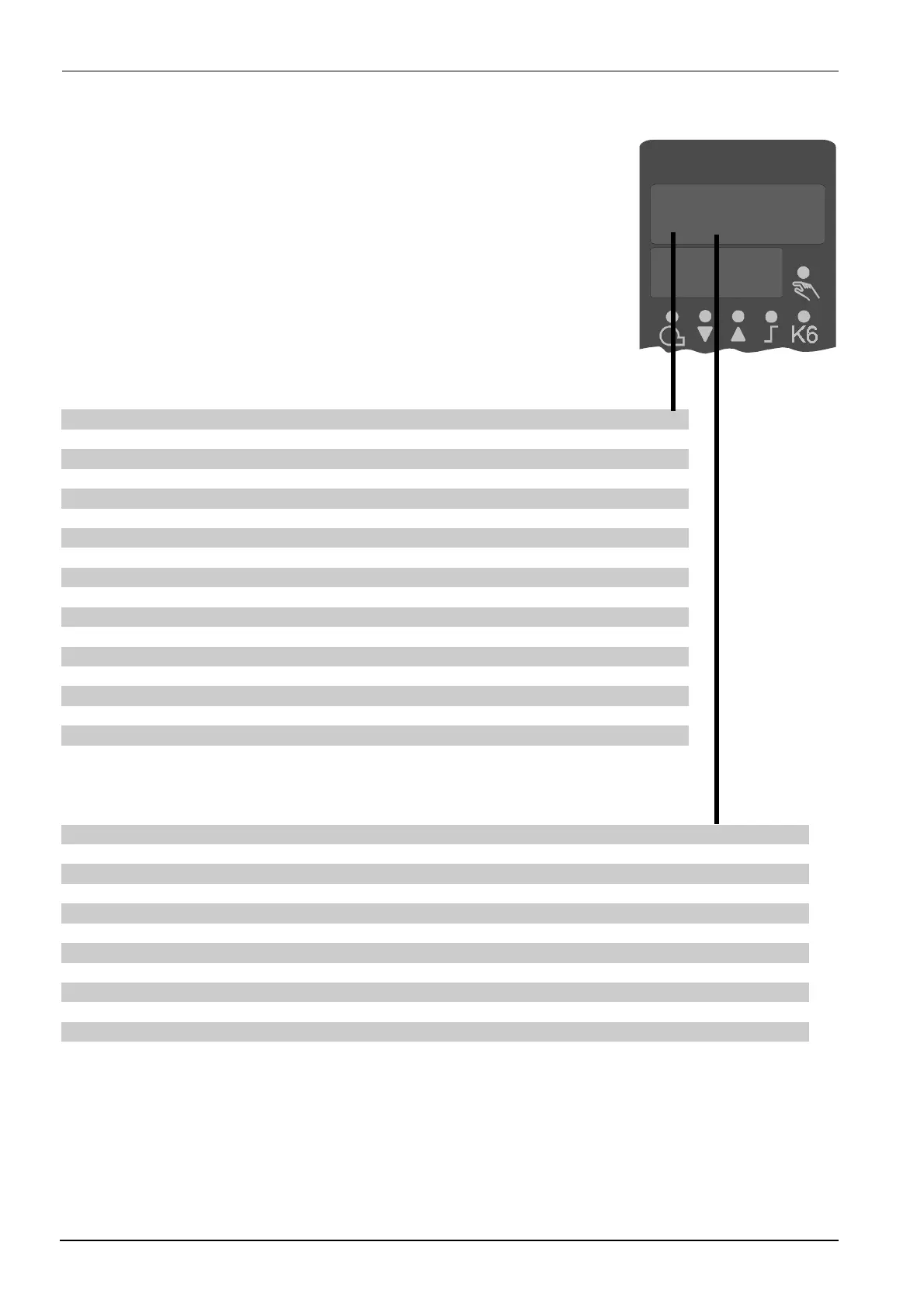
0000
C111
7865p03/0200
Analog input 1
Pt100, 3-wire 0
Pt100, 2-wire 1
Ni100, 3-wire 2
Ni100, 2-wire 3
Pt1000, 3-wire, Landis & Staefa IEC 751 4
Pt1000, 2-wire, Landis & Staefa IEC 751 5
Ni1000, 3-wire, DIN 43760 6
Ni1000, 2-wire, DIN 43760 7
Ni1000, 3-wire, Landis & Staefa 8
Ni1000, 2-wire, Landis & Staefa 9
NiCr-Ni / K A
Cu-CuNi / T b
NiCroSil-NiSil / N C
Fe-CuNi / J d
Standard signal DC 0…20 mA E
Standard signal DC 4…20 mA F
Standard signal DC 0…10 V G
Standard signal DC 0…1 V H
Analog input 2
No function 0
External setpoint, 1 k
Ω
resistance potentiometer 1
External setpoint, DC 0…20 mA 2
External setpoint, DC 4…20 mA 3
External setpoint, DC 0…10 V 4
External setpoint, DC 0…1 V 5
Analog setpoint shift, 1 k
Ω
resistance potentiometer 6
Analog setpoint shift, DC 0…20 mA 7
Analog setpoint shift, DC 4…20 mA 8
Analog setpoint shift, DC 0…10 V 9
Analog setpoint shift, DC 0…1 V A
8.1 C111 inputs

 Loading...


