36/56 CC1B7865E February 10, 2000 Landis & Staefa Division
7. Parameter settings
The parameter is shown on the lower setpoint display (green) and the value on the
upper / actual value display (red).
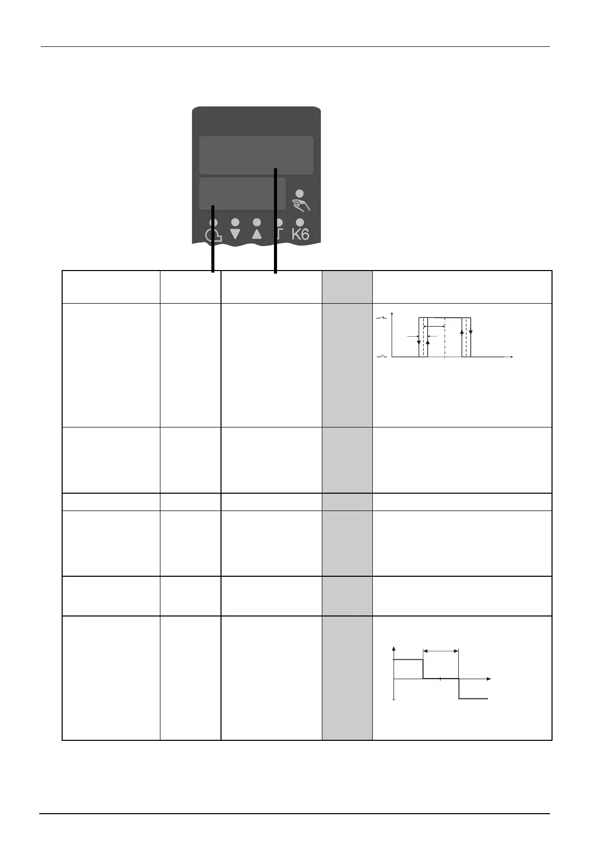
Parameter Display Value range Factory
setting
Remarks
Limit value for limit
comparator
1)
AL
-1999...+9999 digit 0
AL
HYSt
w
Measured value
7865d10e/0300
Output 4
Ö
Chapter 8.2 «
C112
– limit
comparator, controller type, setpoint
«SP1», locking»
Switching differential
for limit comparator
1)
HYSt
0...999.9 digit 1 Switching differential at the edges for
the limit comparators
Ö
Chapter 8.2 «
C112
– limit
comparator, controller type, setpoint
«SP1», locking»
Proportional band
1)
Pb.1
0.1...999.9 digit 10 Affects the P-response of the controller
Derivative time
dt
0...9999 s 80 Affects the D-response of the controller.
Within dt = 0, the controller has no D-
response.
For modulating controllers, dt = rt / 4 or
0 must be entered.
Integral action time
rt
0...9999 s 350 Affects the I-response of the controller.
With rt = 0, the controller has no I-
response
Contact spacing
(dead band)
1)
db
0...999.9 digit 1 For 3-position output
100%
-100%
Y
X
W
db
7865d11/1099
1)
This parameter is affected by the setting of the decimal place.
10
AL
7865p06/0200

 Loading...


