Landis & Staefa Division CC1B7865E February 10, 2000 13/56
4. Electrical connections
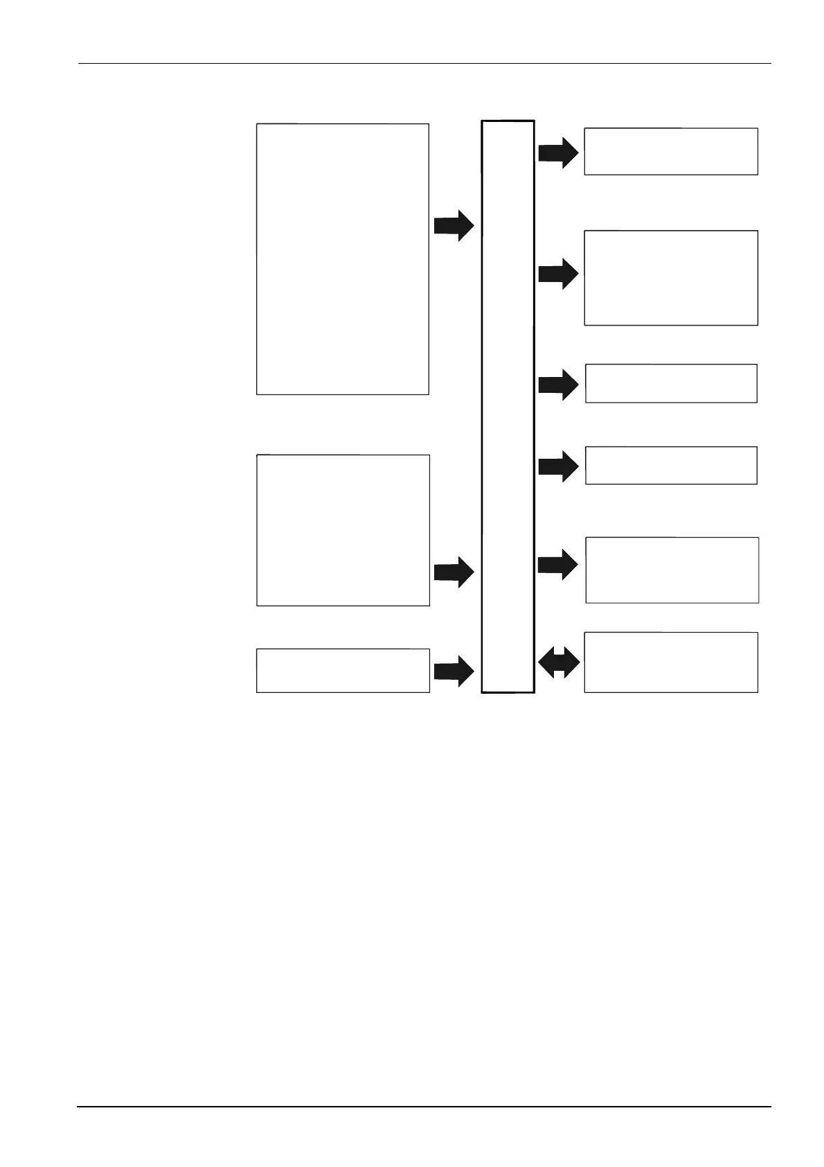
Ω
AC 100 ...240 V,
±10 %, 48...63 Hz
3 analog inputs
2 binary inputs
Operating voltage
Serial interface (optional)
Release of burner
3-position output
Limit comparator
Modulating output (optional)
Transducer supply
RWF40...
7865f01e/0200
Input 1:
Actual value
for Pt100, Ni100, Pt1000,
Ni1000 thermocouples or
standard signals
Input 2:
External setpoint,
setpoint shift
for resistance 0 - 1 k ,
or linearised
standard signals
Input 3:
Outside temperature
for Pt1000, Ni1000
For potential-free
contacts
Input 1:
Operating mode
changeover
Input 2:
Setpoint shift / changeover
Output 1:
- Relay (N.O. contact)
Output 2:
-Relay (reg. unit opens)
Output 3:
- Relay (reg. unit closes)
Output 4:
- Relay (N.O. contact)
DC 24 V, 30 mA
(short-circuit-proof)
Output 5:
Modulating output,
DC 0...10 V, DC 0...20 mA,
DC 4...20 mA
RS-485
MOD bus protocol
Baud rate 9600
4.2 Block diagram

 Loading...


