16/56 CC1B7865E February 10, 2000 Landis & Staefa Division
4. Electrical connections
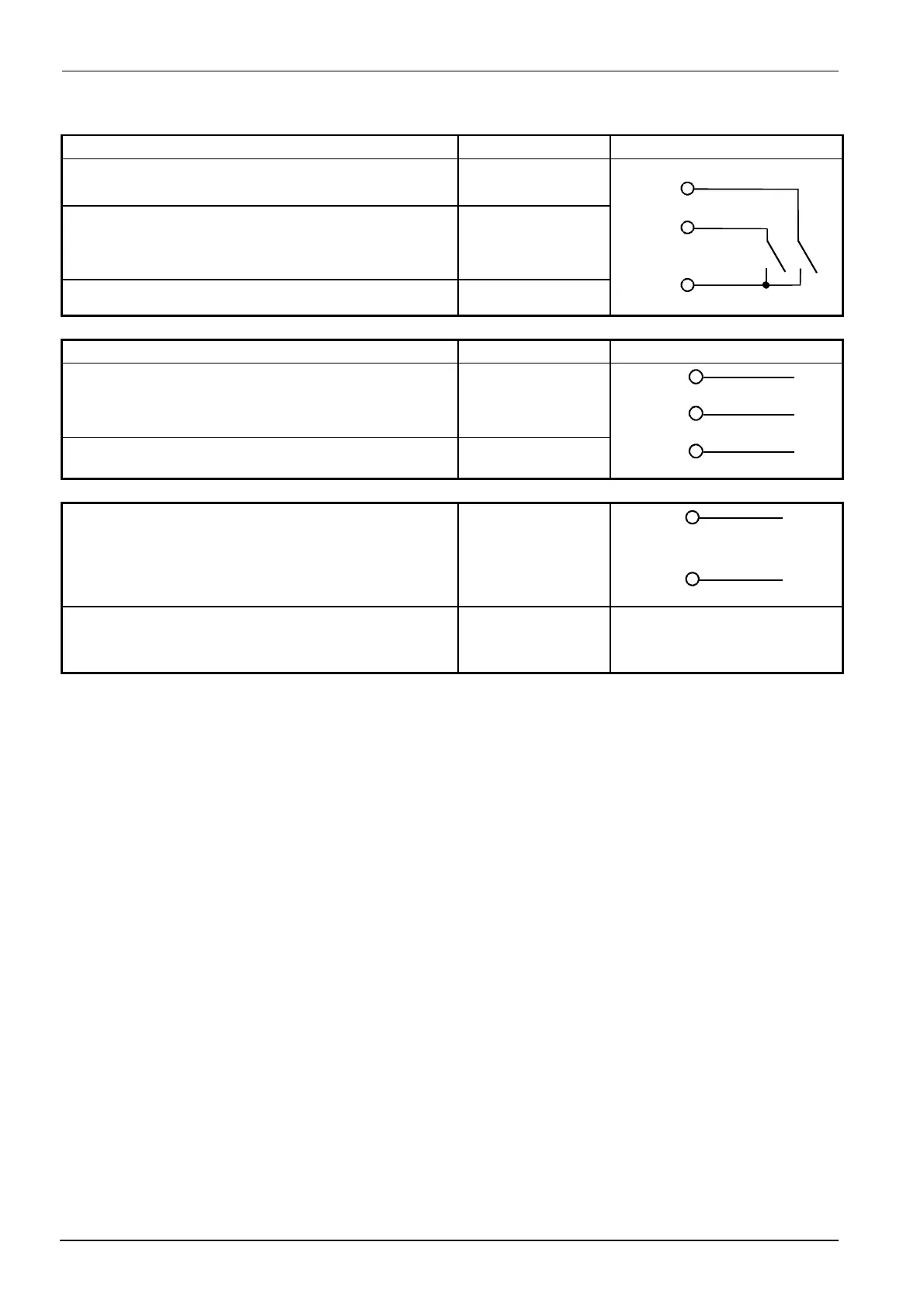
Binary inputs Terminals Connection diagram
Operating mode selector
Ö
Section 5.2 «High-fire operation»
Setpoint shift / changeover
Ö
Sections 5.4.1...5.4.4
Common ground
D1
D2
GND
D1
D2
GND
7865a12/1099
Operating voltage, interface Terminals Connection diagram
Operating voltage
AC 100...240 V ±10 %, 48...63 Hz
Technical earth
L1 line
N neutral
TE
L1
N
TE
7865a18/1099
Operating voltage for transducer G+
G-
G+
G-
+
-
DC 24 V / 30 mA
7865a14/1099
Serial interface
RS-485
CA
CB
CG
RxD / TxD+
RxD / TxD-
GND

 Loading...


