Landis & Staefa Division CC1B7865E February 10, 2000 15/56
4. Electrical connections
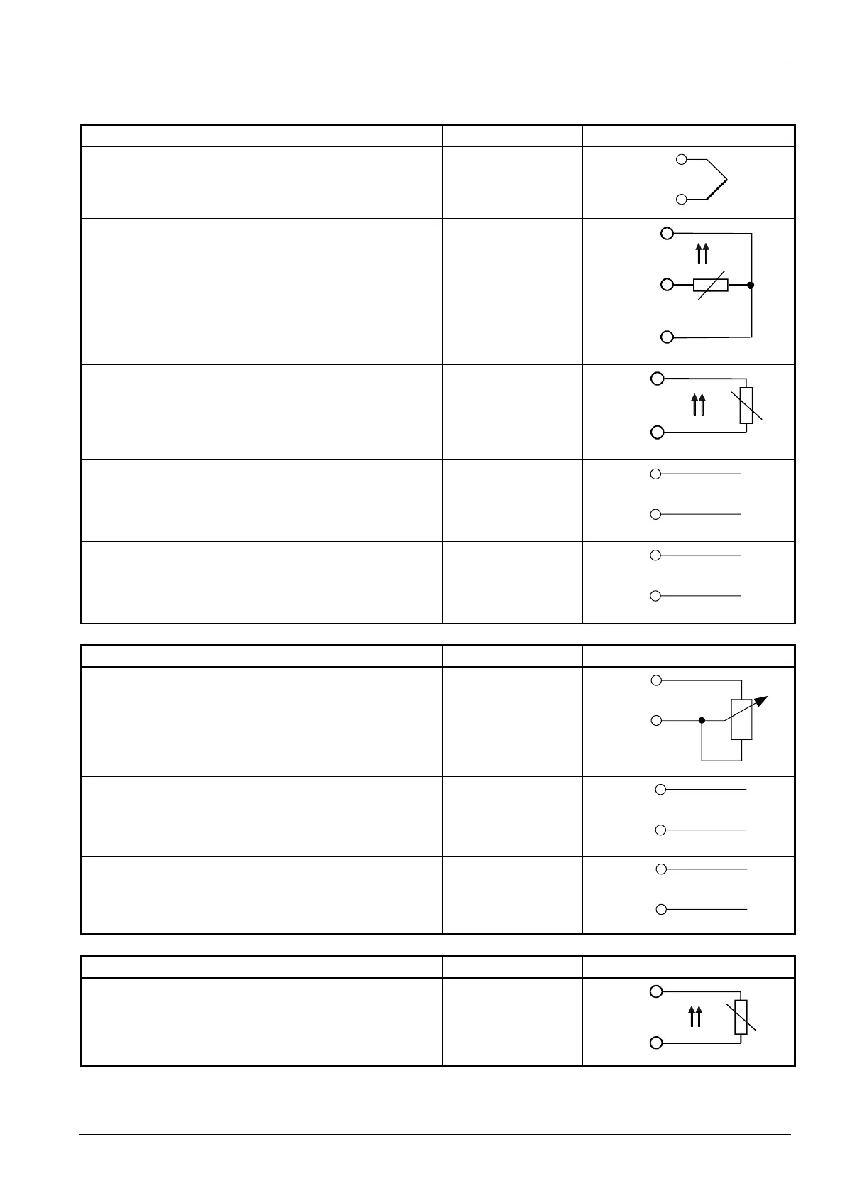
Analog input 1 (actual value) Terminals Connection diagram
Thermocouple I1
M1
I1
M1
+
-
7865a03/1099
Resistance thermometer in 3-wire circuit M1
G1+
I1
ϑ
M1
G1+
I1
7865a04/1099
Resistance thermometer in 2-wire circuit, line
compensation through offset correction (OFF1)
M1
G1+
ϑ
M1
G1+
7865a05/1099
Current input
DC 0...20 mA, 4...20 mA
I1
M1
I1
M1
+
-
7865a06/1099
Voltage input
DC 0...1 V, 0...10 V
U1
M1
U1
M1
+
-
7865a07/1099
Analog input 2 (setpoint and setpoint shift) Terminals Connection diagram
Resistance potentiometer
Offset correction (OFF2)
XB6 start
M6 slider
M6 end
M6
XB6
A
S
E
7865a08/1099
Current input
DC 0..20 mA, 4...20 mA
XB6
M6
XB6
M6
+
-
7865a09/1099
Voltage input
DC 0...1 V, 0...10 V
XU6
M6
XU6
M6
+
-
7865a10/1099
Analog input 3 (outside temperature) Terminals Connection diagram
Resistance thermometer in 2-wire circuit, line
compensation through offset correction (OFF3)
B9
M9
ϑ
B9
M9
7865a13/1099

 Loading...


