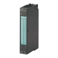
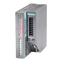
IM 155-6 PN ST interface module (6ES7155-6AU01-0BN0)
26 Equipment Manual, 10/2020, A5E03576904-AE
Interrupts, diagnostics, error, and system
messages
5.1 Status and error displays
LED display
The following diagram shows the LED display on the interface module and the BusAdapter.
Figure 5-1 LED display on the interface module and BusAdapter
Meaning of the LEDs
The meaning of the status and error messages is described in the following tables.

 Loading...


