Installation and Maintenance UMMPS-1
January 2003 2
Operation
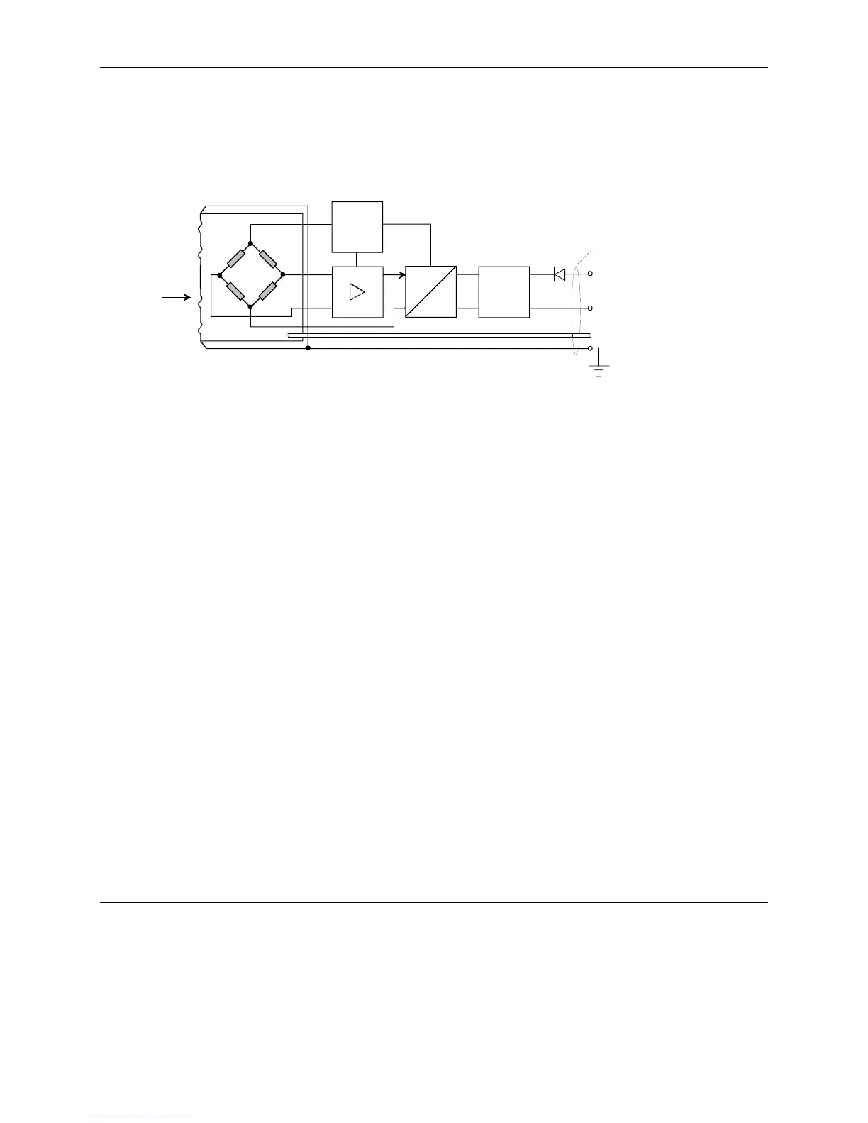
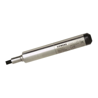
The hydrostatic pressure felt by the sensor is proportional to submersion depth. The pressure of the process medium
deflects the stainless steel diaphragm at the tip of the transmitter. This deflection is sensed by a piezo-resistive
bridge. The diaphragm and bridge also sense the atmospheric (barometric) pressure supplied through a vent pipe in
the connecting cable.
U
Const.
U
I
EM
Diaphragm
Sensor
Vent Pipe
Shield
+ Brown
- Blue
I
o
, U
B
p
MG00415b
Cable Jacket
FIGURE 2 Block Diagram
The bridge output voltage is a pressure differential signal that is then converted to a 4-20 mA output current. The
circuit board is sealed in the housing.
The transmitter is powered from a user-supplied 10-36 Vdc source. Diodes at the transmitter input protect against
reverse polarity and over voltage.
An optional junction box provides screw terminals for cable termination and for connecting to a receiving
instrument, such as a Siemens Model 353 Process Automation Controller. The cable shield is connected to the
housing and is connected by the user to earth ground. Within the junction box, the vent pipe is exposed to
atmospheric pressure.



 To Next Page