UMMPS-1 Installation and Maintenance
January 2003 3
Installation
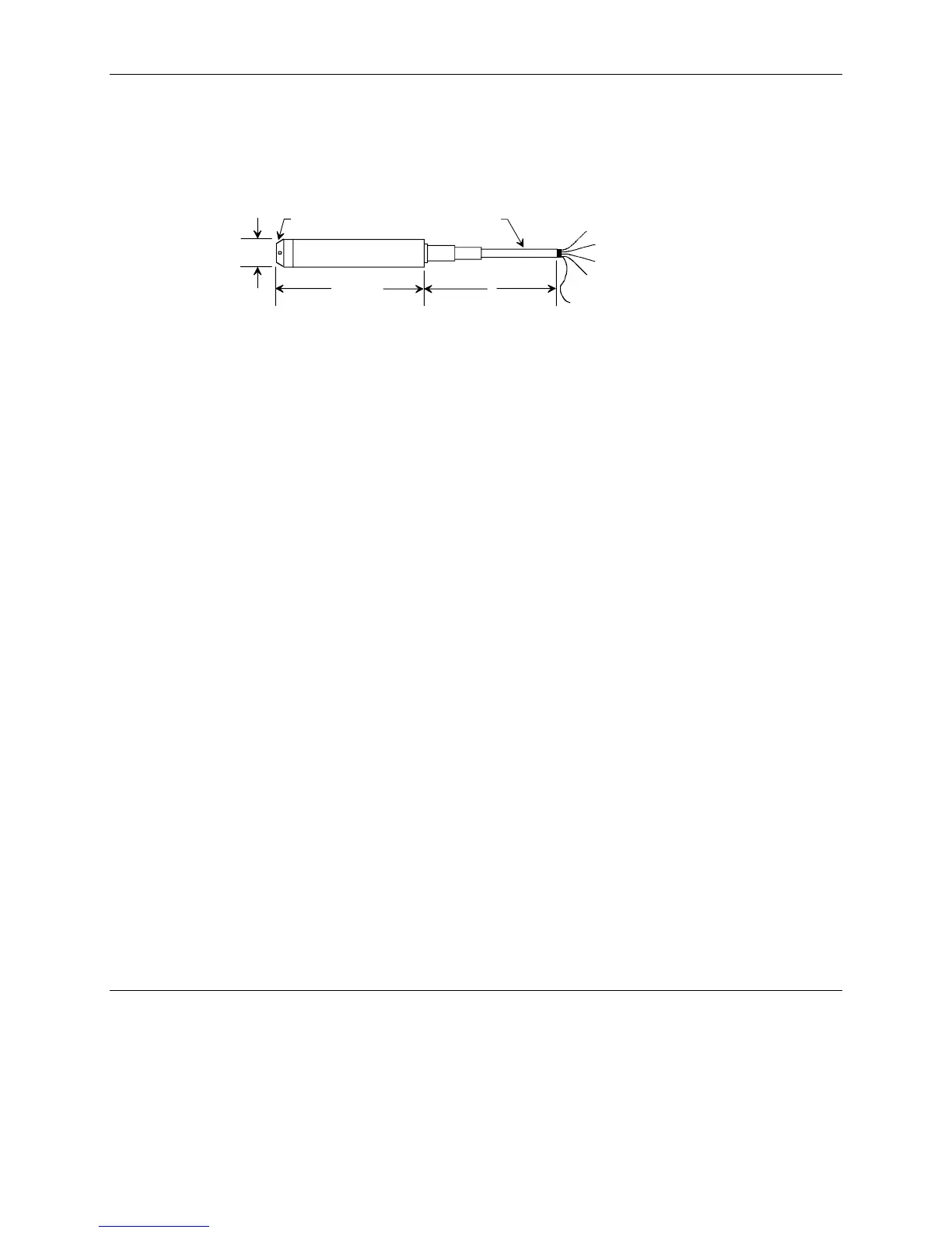
The transmitter is installed suspended on the cable. The cable is routed through a cable hanger and into the junction
box as shown in figure 1. Figure 3 shows transmitter dimensions.
+ Brown
Vent Pipe
Cord, White
- Blue
Shield
158 mm
6.22 in.
L
Protective Cap Cable Sheath
27 mm
1.06 in.
MG00416b
1. Dimensions are in millimeters and inches.
2. Cable sheath 8.3 mm / 0.23 in. diameter; black, HFFR
3. Flexible cable with 0.5 mm
2
/ 10 AWG cross-section
4. Vent pipe 1 mm / 0.04 in. inner diameter
5. Protective cap with 4 x 3 mm / 0.15 x 0.12 in. diameter holes; black, PA
FIGURE 3 Transmitter Dimensions
In a moving medium, transmitter location must be fixed to prevent measuring errors. To minimize movement, install
a guide tube, add a weight on the transmitter (maximum tensile force on the cord is 65 lbs), or install a bracket
between the transmitter and the vessel.
Anchor the cable above the vessel with the cable hanger; see the Cable Hanger section later in this manual. Connect
the cable leads to the junction box; see the Junction Box section later in this manual. Mount the junction box in a
location compatible with its degree of protection (IP 54).
There are four inlet holes in the protective cap at the diaphragm end of the transmitter. These holes must be open to
the medium and free of congealed material and contaminants (e.g. dust, dirt, grease) to ensure transmitter accuracy.
If gelled or solidified material is likely to accumulate at the bottom of the vessel, the tip of the sensor should be
elevated above the level at which the vessel will be drained and cleaned.