Installation and Maintenance UMMPS-1
January 2003 4
Wiring
WARNING
Electrical shock hazard
Hazardous voltage can cause death or serious injury.
Remove power from all wires and terminals before working
on this equipment.
1. Remove power from all wires and terminals to eliminate any electrical shock hazard.
2. Route the transmitter cable through the cable hanger and into the junction box.
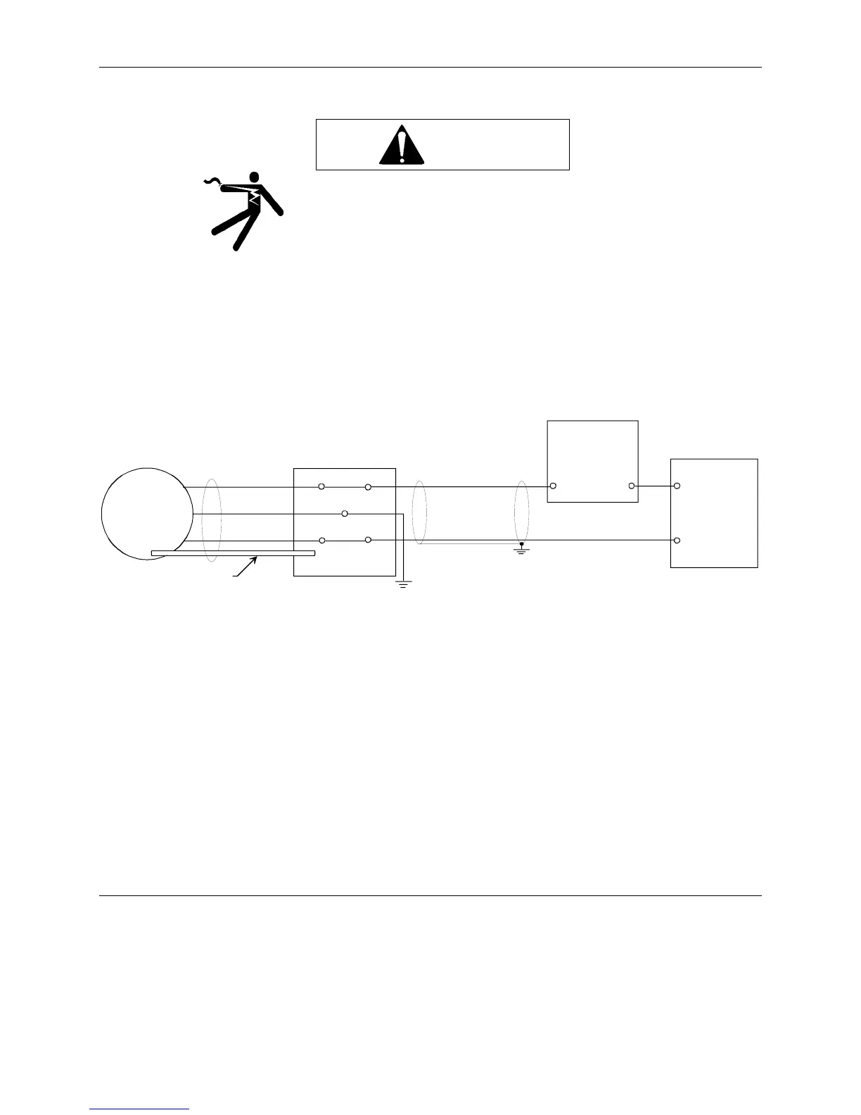
3. Connect the transmitter cable to the junction box. See Figures 3 and 4.
Blue wire to Terminal 1 (-)
Brown wire to Terminal 2 (+)
Shield wire to Ground
1
2
1
2
Blue
Screen
Brown
Transmitter
Vent Pipe
To Atmospheric Pressure
+
+
_
_
Junction Box
User-Supplied
10-36 Vdc
Power Supply
+
_
Controller,
Recorder, or
other process
instrument
MG00417a
GND
FIGURE 4 Electrical Connections
4. Clamp the cord between the two screws provided in the box.
5. Find the end of the vent pipe. This end of the pipe must be open and exposed to atmospheric pressure.
6. Connect a user-supplied 10-36 Vdc power supply to terminals 1 and 2 in the junction box. The resistance value
for the maximum load depends on the voltage U
B
. It is determined by the following equation:
U
B
- 10 V
R
max
= ————— (kOhm)
20 mA
Calibration
The transmitter has been calibrated at the factory to the user-specified measuring range. It cannot be re-calibrated.