7XT3400-0*A00/DD English
C53000-B119U-C130-1 7
Installation Hints
Connect the relay solidly with low impedance to the protective earth continuity system of the
switch gear!
Make connections via the screwed or snap-in terminals. Observe labelling of the individual
terminals to ensure correct location; observe the max. permissible conductor cross-sections
and bending radius.
The screw-type terminals can be used without wire end ferrules. Pin-end connectors
generally must not be used.
The use of the screwed terminals is recommended; snap-in connection requires special
tools and must not be used for field wiring unless proper strain relief is ensured.
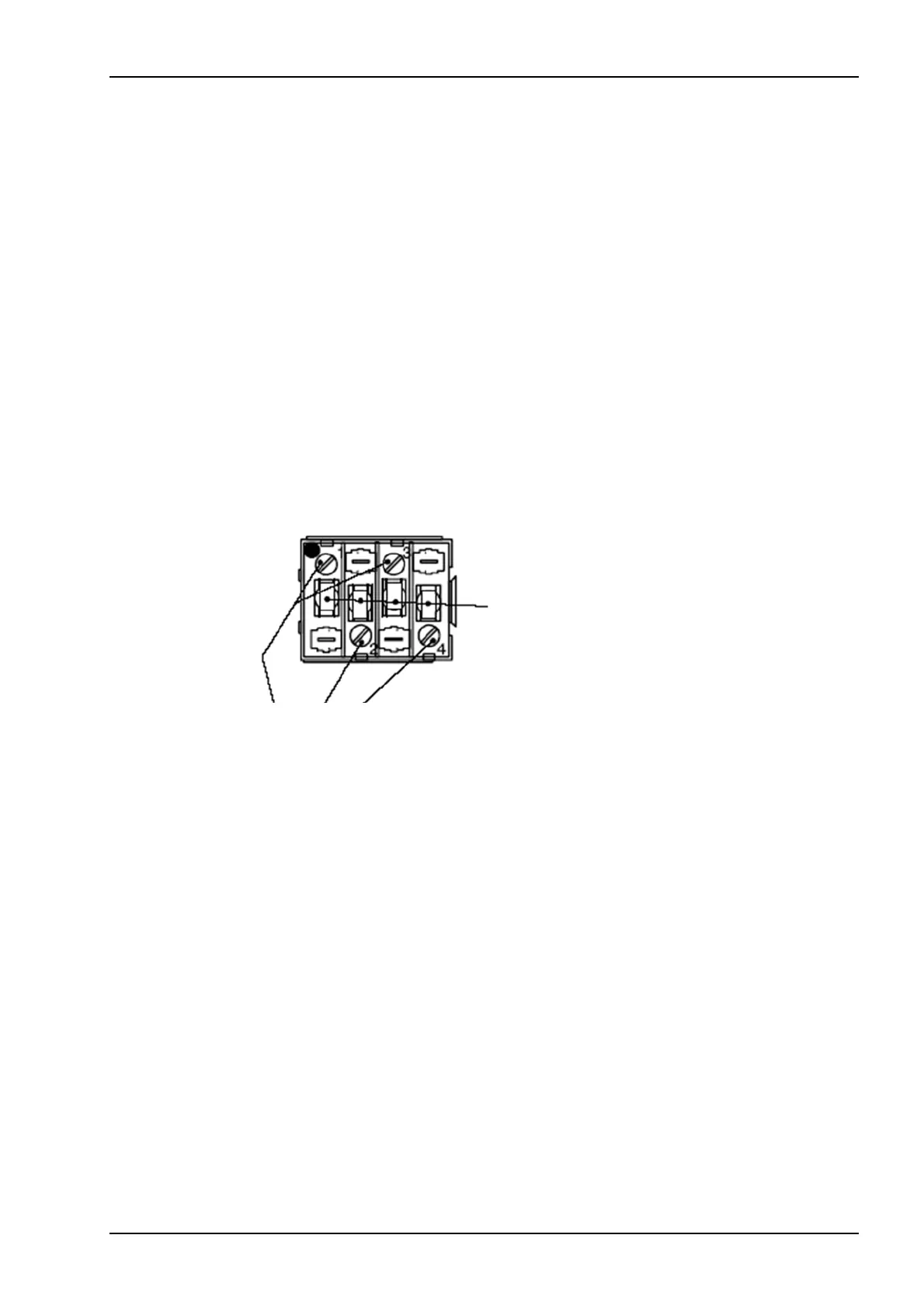
The terminals of the flush mounting case are 4-pole voltage connector modules.
The terminal screws are tightened at delivery, and must be loosened before inserting any
wire.
Figure 1 Connection of the voltage module
Terminal cells for
screwed connection
Terminal screws
 Loading...