EasyManua.ls Logo

Siemens 7XV75 - User Manual

Siemens 7XV75
13 pages
Print Icon
To Next Page IconTo Next Page
Loading...
7XV75 Test Switch
1 Siemens AG March 2021
7XV75 Test Switch
Notes on Safety
This catalogue contains notes that must be adhered to for your own personal safety and to avoid damage to property.
However, it does not constitute a complete description of all safety measures required for installation, service, and mainte-
nance of the equipment (module, device) in question. Details are to be taken from the device manual and those are manda-
tory.
Qualified Electrical Engineering Personnel
Only qualified electrical engineering personnel may commission and operate the equipment (module, device) described in
this document. Qualified electrical engineering personnel in the sense of this document are people who can demonstrate
technical qualifications as electrical technicians. These persons may commission, isolate, ground and label devices, sys-
tems and circuits according to the standards of safety engineering.
Use as Prescribed
The equipment (device, module) may only be used for such applications as set out in the catalogs and the technical de-
scription, and only in combination with third-party equipment recommended and approved by Siemens.
Problem-free and safe operation of the product depends on the following:
Proper transport
Proper operation and maintenance
Proper storage, setup, and installation
Statement of Conformity
Further standards
IEC 60255, VDE 0435
WARNING
Danger of severe personal injury or substantial damage to property
Hazardous voltages may occur in devices and modules during operation depending on the design and appli-
cation.
Always observe the instructions given in “Qualified Electrical Engineering Personnel” below.
WARNING
Danger of death, personal injury or substantial property damage
Non-observance of the following measures can result in death, personal injury or substantial property
damage.
The equipment must be grounded at the grounding terminal before any connections are made.
If you require further information, or if particular problems occur that are not handled in sufficient depth in the instructions
of the respective product, you can request help through your local Siemens Office or representative.
Low-voltage Directive 2014/35/EU
RoHS Directive 2011/65/EU R
The conformity is based on the compliance with
the following harmonized standards
EN 50581 and EN 60255-27
Question and Answer IconNeed help?

Do you have a question about the Siemens 7XV75 and is the answer not in the manual?

Overview

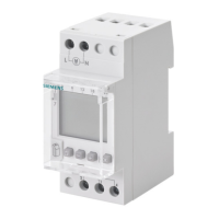
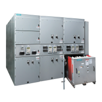
The Siemens 7XV75 Test Switch is a crucial component for testing protection devices using secondary injection test sets. It is designed for flush mounting and offers various configurations to suit different protection schemes.

Function Description

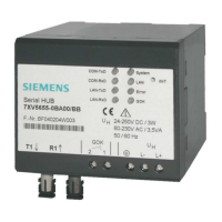
The 7XV75 test switch facilitates the testing of protection devices by providing a means to interrupt and apply signals to the device under test. It includes C.T. circuits and command contacts. Switches on the front panel allow for the interruption of current and voltage inputs, as well as the circuits of the protection device. Through a plug-in connector on the front, currents and voltages can be fed by an injection test set, enabling the testing of various commands and indications.

Important Technical Specifications

General Device Data:

  • Rated operating voltage Vc: 250 V AC/DC
  • Rated operating current Ic: Max 5 A
  • Rated breaking capacity: For 1 s: 30 A; For 10 s: 20 A
  • Continuous current: 60 A
  • Overvoltage category (IEC 60255-27): III
  • Operating Altitude: Max 2000 m
  • Pollution Degree: 2
  • Protection: Class 1

Electrical Tests (IEC 60255-27, Edition 2.0):
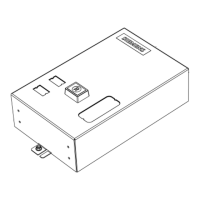
  • Voltage test (routine test and type test): 2.5 kV, 50 Hz
  • Impulse voltage (type test): 5 kV (peak value), 1.2/50 µs, 0.5 J, 3 positive and 3 negative impulses at intervals of 5 s
  • Insulation resistance measurement: 500 V DC, For 1 min, ≥100 MOhm

Construction:

  • Metal case: 7XP20
  • Dimension: 144 x 172 x 172 mm (W x H x D)
  • Weight: Approx. 3.4 kg
  • Protection type acc. to IEC 60529:
    • With closed cover: IP40
    • With open cover: IP20
    • For operator protection: IP2x for terminals

Mechanical Stress Tests (IEC 60255-21 and IEC 60068):

  • Vibration (IEC 60255-21-1, class II; IEC 60068-2-6):
    • Sinusoidal
    • 10 Hz to 58 Hz: ± 0.075 mm amplitude
    • 58 Hz to 150 Hz: 1 g acceleration
    • Frequency sweep rate: 1 octave/min
    • 20 cycles in 3 orthogonal axes
  • Shock (IEC 60255-21-2, class I; IEC 60068-2-27):
    • Semi-sinusoidal
    • 5 g acceleration, duration 11 ms, each 3 shocks in both directions of the 3 axes
  • Seismic vibration (IEC 60255-21-3, class I; IEC 60068-3-3):
    • Sinusoidal
    • 1 Hz to 8 Hz: ± 3.5 mm amplitude (horizontal axis)
    • 1 Hz to 8 Hz: ± 1.5 mm amplitude (vertical axis)
    • 8 Hz to 35 Hz: 0.5 g acceleration (horizontal axis)
    • 8 Hz to 35 Hz: 0.2 g acceleration (vertical axis)
    • Frequency sweep rate: 1 octave/min
    • 1 cycle in 3 orthogonal axes
  • Vibration and shock during transport (IEC 60255-21 and IEC 60068):
    • Vibration (IEC 60255-21-1, class II; IEC 60068-2-6):
      • Sinusoidal
      • 5 Hz to 8 Hz: ± 7.5 mm amplitude
      • 8 Hz to 150 Hz: 2 g acceleration
      • Frequency sweep rate: 1 octave/min
      • 20 cycles in 3 orthogonal axes
    • Shock (IEC 60255-21-2, class I; IEC 60068-2-27):
      • Semi-sinusoidal
      • 15 g acceleration, duration 11 ms, each 3 shocks in both directions of the 3 axes
    • Continuous bump (IEC 60255-21-2, class I; IEC 60068-2-29):
      • Semi-sinusoidal
      • 10 g acceleration, duration 16 ms, each 1000 shocks in both directions of the 3 axes

Climatic Stress Tests:

  • Permissible temperature during service: -20 °C to + 70 °C

Voltage Terminals:

  • Recommended use of the screwed terminals:
    • Stripping length (without conductor sleeve): L = 10 mm (0.39 in) or L = 12 mm (0.47 in); max. wire cross-section AWG 16 (1.5 mm²), use copper conductors only.
    • When using conductor sleeves: Geometry for terminal cells according to EN 60947-7, class A1 must be complied with.
    • Permissible tightening torque at the terminal screw: 0.8 Nm (7.1 lb.in.)
    • Sleeves length (wire range): min. 10 mm (0.39 in) (e.g. DIN 46228-E1.5-10)

Current Terminals:

  • Recommended use of the screwed terminals:
    • Stripping length (without conductor sleeve): L = 12 mm (0.47 in) or L = 14 mm (0.55 in); max. wire cross-section AWG 12 (4.0 mm²), use copper conductors only.
    • When using conductor sleeves: Geometry for terminal cells according to EN 60947-7, class A4 must be complied with.
    • Permissible tightening torque at the terminal screw: 1.2 Nm (10.6 lb.in.)
    • Sleeves length (wire range): min. 12 mm (0.47 in) (e.g. DIN 46228-E4-12)

Grounding Screw:

  • Permissible tightening torque at the grounding screw: 1.2 Nm (10.6 lb.in.)

Nominal Values:

  • The nominal values shown on the name plate of the device must be observed.

Operating Temperature:

  • Permissible temperature range for permanent operation: -5 °C (BU -10 °C (+10 °F)) to +55 °C (+23 °F to +131 °F)

Operating Altitude:

  • Maximum altitude above sea level: 2000 m

Degree of Protection (acc. to IEC 60529):

  • For use in environment with degree of pollution 2.

Usage Features

The 7XV75 Test Switch is available in several flush-mounting versions, catering to diverse protection applications:

  • For feeder protection without an open starpoint: This version is suitable for standard feeder protection schemes where the neutral point is not accessible or not required.
  • For feeder protection without an open starpoint and with additional contacts: This variant provides extra contacts for more complex control or signaling requirements in feeder protection.
  • For feeder protection without an open starpoint for two CT cores or separate earth fault CT: Designed for applications requiring separate current transformer cores for different protection functions or dedicated earth fault detection.
  • For feeder protection with an open starpoint: Used in systems where the neutral point is accessible and utilized for protection.
  • For feeder protection with an open starpoint and independent switchable trip and c.t. circuits: Offers enhanced flexibility with independently switchable trip and current transformer circuits, allowing for more granular testing and operational control.
  • For a 3-winding transformer differential protection: Specifically configured for differential protection schemes involving three-winding transformers.
  • For feeder protection without an open starpoint, with 4th CT and 4th VT input (three-stage test switch): A comprehensive version for advanced feeder protection, including inputs for a fourth current transformer and voltage transformer, and featuring a three-stage test switch.

The test device is versatile regarding auxiliary supplies, supporting a wide range from 24 V to 250 V AC/DC. This eliminates the need for selecting different power supply models, simplifying procurement and installation.

Maintenance Features

  • Grounding: The equipment must be grounded at the grounding terminal before any connections are made. This is a critical safety measure to prevent electrical hazards.
  • Robust Construction: The metal case and specified protection types (IP40 with closed cover, IP20 with open cover, IP2x for operator protection) ensure durability and protection against environmental factors and accidental contact.
  • Compliance with Standards: Adherence to IEC 60255-27, IEC 60068, and EN 60947-7 standards ensures reliability and compatibility with established electrical engineering practices.
  • Clear Connection Diagrams: The manual provides detailed connection diagrams for various models (e.g., 7XV7500, 7XV7501, 7XV7502, 7XV7503, 7XV7506, 7XV7507, 7XV7508), which are essential for correct installation and troubleshooting. These diagrams illustrate the wiring for current and voltage inputs, trip circuits, annunciation, and reclose commands.
  • Accessories: Connecting cables with 16-pole Harting plugs and isolated banana connectors or cable end sleeves are available, simplifying the connection to test sets and protection devices. These accessories are designed with cable marks for easy identification and correct wiring.

Notes on Safety:

  • This catalogue contains notes that must be adhered to for your own personal safety and to avoid damage to property.
  • However, it does not constitute a complete description of all safety measures required for installation, service, and maintenance of the equipment (module, device) in question. Details are to be taken from the device manual and those are mandatory.
  • Warning: Danger of severe personal injury or substantial damage to property. Hazardous voltages may occur in devices and modules during operation depending on the design and application. Always observe the instructions given in "Qualified Electrical Engineering Personnel" below.
  • Qualified Electrical Engineering Personnel: Only qualified electrical engineering personnel may commission and operate the equipment (module, device) described in this document. Qualified electrical engineering personnel in the sense of this document are people who can demonstrate technical qualifications as electrical technicians. These persons may commission, isolate, ground and label devices, systems and circuits according to the standards of safety engineering.
  • Use as Prescribed: The equipment (device, module) may only be used for such applications as set out in the catalogs and the technical description, and only in combination with third-party equipment recommended and approved by Siemens.
  • Problem-free and safe operation of the product depends on the following: Proper transport, proper operation and maintenance, proper storage, setup, and installation.
  • Warning: Danger of death, personal injury or substantial property damage. Non-observance of the following measures can result in death, personal injury or substantial property damage. The equipment must be grounded at the grounding terminal before any connections are made.

If you require further information, or if particular problems occur that are not handled in sufficient depth in the instructions of the respective product, you can request help through your local Siemens Office or representative.

Siemens 7XV75 Specifications

General IconGeneral
BrandSiemens
Model7XV75
CategorySwitch
LanguageEnglish

Related product manuals