V1.0 Page 6 of 38 ICM MP CC ST
A35-A36-A40 Company Confidential 09/01
4. Radio Part
The radio part converts the I/Q base band signals supplied, by the logic (EGOLD+) Notes
into RF-signals with characteristics as per the GSM recommendation
(transmission) which are radiated by the antenna.
Or the radio part converts the received GMSK signal, supplied by the antenna
into I/Q base band signals, which can be further processed by the logic (EGOLD+).
The radio part is designed for Dual Band operation and can therefore serve the
frequency bands EGSM900 and GSM1800. The radio part can never transmit and
receive in both bands simultaneously. However, the monitor time lot can be selected
independently of the frequency band.
Transmitter and receiver are of course never operated simultaneously.
The radio part consists of the following blocks:
• Power supply (RF-Voltage regulators)
• Synthesizer (partly located in SMARTI)
• Receiver (partly located in SMARTI)
• Transmitter (Up conversion loop partly located in SMARTI)
• Transmitter (Power amplifier)
• Antenna Switch
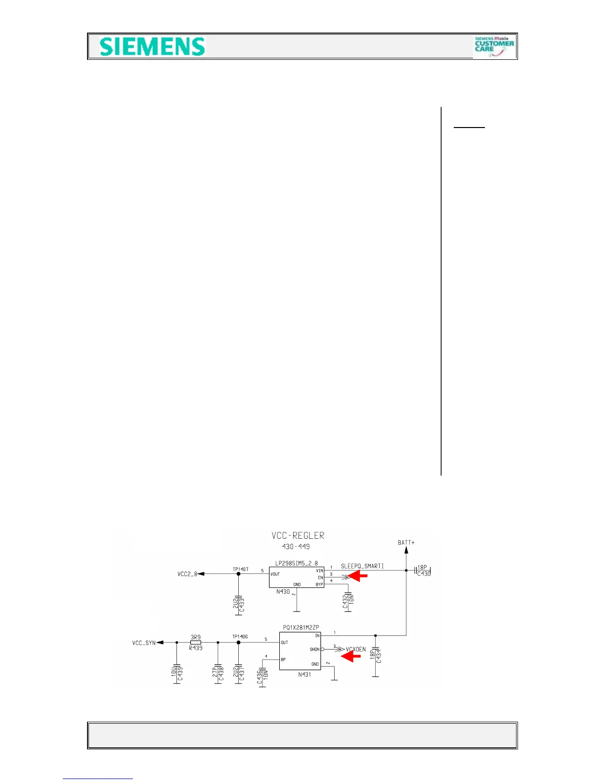
4.1 Power Supply RF-Part
Two voltage regulators (N430/431) with a nominal output voltage of 2.8V are
used, to perform the required “RF-Voltages”.
The voltage regulator N430 is activated via SLEEPQ_SMARTI provided by the
EGOLD+ (TDMA-Timer H12).
The voltage regulator N431 is activated via VCXOEN provided by
the EGOLD+ (Functional P7).
The name of the voltages are: a) VCC_SYN activated by VCXOEN
and b) VCC2_8 activated by SLEEPQ_SMARTI
For both voltages BATT+ is required.
 Loading...