V1.0 Page 8 of 38 ICM MP CC ST
A35-A36-A40 Company Confidential 09/01
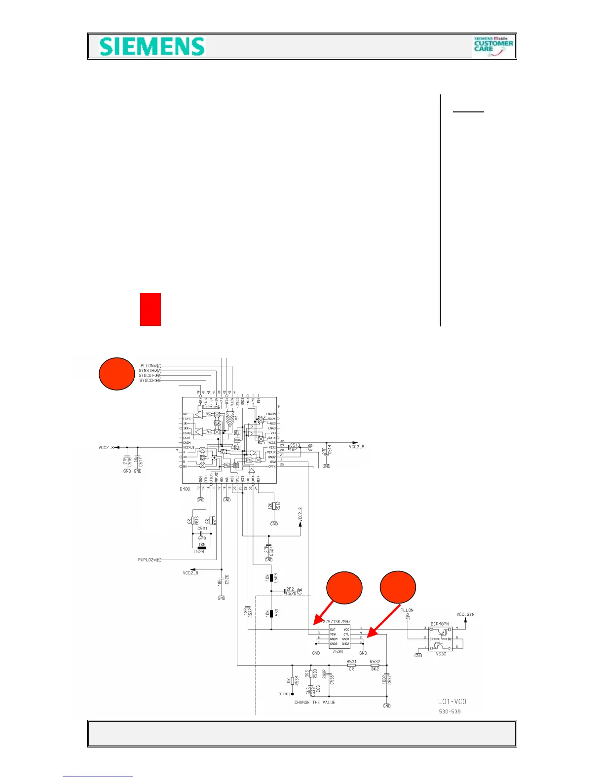
4.2.2 Synthesizer : LO1
The first local oscillator (LO1) consists of the D400 PLL part, a loop filter Notes
and a VCO (Z530) module. This LO1 circuit generates frequencies from 1445MHz
to 1520MHz for GSM 1800 RX-operation, and from 1285MHz to 1361MHz
for the other operations. The Z530 is switchable to select the channels in stages of
200kHz. The VCO module is activated by the EGOLD+ signal
PLLON (TDMA-Timer J12) via V530. The switching between GSM900 and GSM1800 is
realised by the OSW signal from the SMARTI (D400 pin 21),
The channel programming happens via the EGOLD+. signals SYGCCL, SYGCDT,
SYNSTR.
The VCO output signal fulfils three functions:
a) It enables the SMARTI IC to mix the RXIF-Frequency (360 MHz)
b) It enables the SMARTI IC to mix the TXIF-Frequency (424 MHz)
c) It ensures with the help of the 13MHz signal and the SMARTIs PLL part the
frequency stability by generating a control voltage at (SMARTI pin 20)
The required voltages are: VCC2_8 for D400 provided by N430.
VCC_SYN for the VCO provided by N431
The picture 4221 shows the VCO output signal
The picture 4222 shows the control voltage
The picture 4223 shows the programming signals for the PLL
 Loading...