Company Confidential s Com
Copyright 2005© Siemens AG
Page 11 of 53
TD_Repair_L2.5_A70_A75_R1.0.pdf Release 1.0
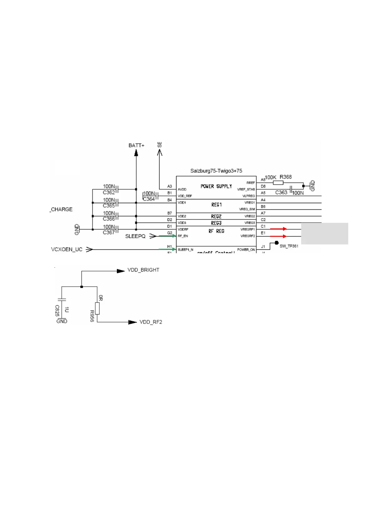
6.2 Power Supply RF-Part
The voltage regulator for the RF-part is located inside the ASIC D361.It generates the
required 2,8V “RF-Voltages” named VDD_RF1 and VDD_RF2. VDD_RF2 is passed via a 0Ω
resistor and renamed as VDD_BRIGHT as operating voltage for the BRIGHT. The voltage
regulator is activated as well as deactivated via SLEEPQ
(TDMA-Timer R11) and VCXOEN_UC
(M4)
provided by the EGOLDlite. The temporary deactivation is used to extend the stand by
time.
Circuit diagram
VDD_RF1
DD_RF2
6.3 Frequency generation
Synthesizer: The discrete VCXO (26MHz)
The A70/A75 mobile is using a reference frequency of 26MHz. The generation of the 26MHz
signal is done via a VCO (Z950).
TP (test point) of the 26MHz signal is the TP 820
The oscillator output signal 26MHz_RF is directly connected to the BRIGHT IC
(ball B9,. C9) to
be used as reference frequency inside the Bright (PLL). The signal leaves the Bright IC as
RF_SIN26M
(ball G9) to be further used from the EGOLDlite (D171 (C8)).

 Loading...