Company Confidential s Com
Copyright 2005© Siemens AG
Page 13 of 53
TD_Repair_L2.5_A70_A75_R1.0.pdf Release 1.0
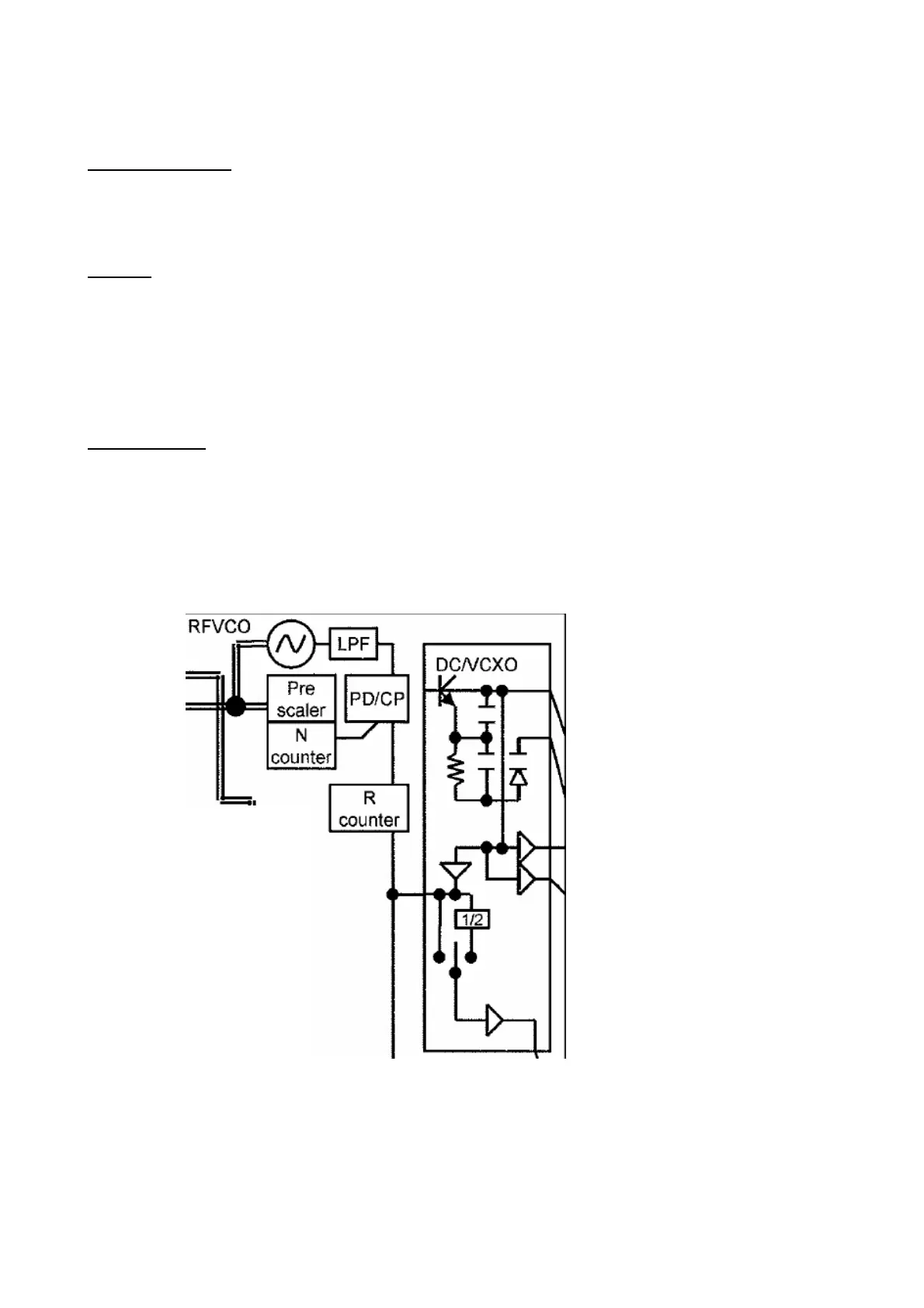
Synthesizer: LO1
First local oscillator (LO1) consists of a PLL and VCO inside Bright (D903) and an internal
loop filter
RF PLL
The frequency-step is 400 kHz in GSM1800 mode and 800kHz in EGSM900 mode due to the
internal divider by two for GSM1800 and divider by four for EGSM900. To achieve the
required settling-time in GPRS operation, the PLL can operate in fastlock-mode a certain
period after programming to ensure a fast settling. After this the loopfilter and currents are
switched into normal-mode to get the necessary phasenoise-performance. The PLL is
controlled via the tree-wire-bus of Bright VI E.
RFVCO (LO1)
The first local oscillator is needed to generate frequencies which enable the transceiver IC to
demodulate the receiver signal and to perform the channel selection in the TX part. The VCO
module is switched on with the signal PLLON. The full oscillation range is divided into 256
sub-bands To do so, a control voltage for the LO1 is used, gained by a comparator. This
control voltage is a result of the comparison of the divided LO1 and the 26MHz reference
Signal. The division ratio of the dividers is programmed by the EGOLDlite, according to the
network channel requirements.

 Loading...