- 3 -
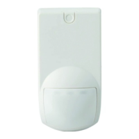
ADM-Q12T motion detector
The detector detects movement in the
room under surveillance
7
and initiates
an alarm. It responds most sensitively to
movement in the directions indicated by
arrows
7
B / D. Antimask ensures that
manipulation close to the detector
(0.5 meters) is reliably detected. The
back tamper recognizes if the detector is
removed with force.
Prerequisites
The detector should be installed by peo-
ple with specialist knowledge and in
compliance with valid regulations.
The detector is only intended
for inside rooms. Note the
positioning instructions
6
.
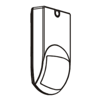
Opening the detector
1. Check the scope of delivery
1
.
2. Slide up the screw-on cover
2
A and
loosen the screw
2
B.
3. Pull the housing front
2
D off the base
2
C.
Fitting the detector
1. Fit the mounting base
2
C as follows:
- Define type of fastening
4
A / B. (also
refer to mounting bracket option)
- Break open three fixing holes.
- Break open aperture for cable
feedthrough
4
D.
- Fit mounting base at the proposed
height.
The mounting base should be
secured using two screws
4
A / B and the back tamper
with one screw
4
C.
2. Wire the power supply, alarm and
tamper connections according to the
options provided by the panel
8
.
Please note the end-of-line
usage guidelines for simplified
installation using the end-of-
line (EOL) concept
5
E /
9
.
3. Fold front
2
D back onto mounting
base
2
C and secure with screw
2
B.
Slide down screw-on cover
2
A.
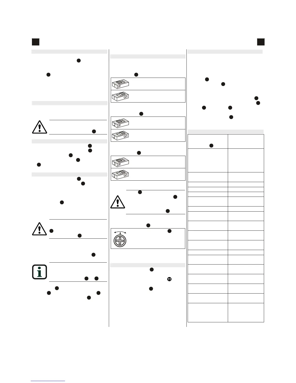
Programming
To adjust the settings to the application,
move the switches into the correspond-
ing positions:
LED on / off
5
A
LED only indicates motion in
walk test mode.
LED lights up when detecting
motion.*
* factory setting
PIR sensitivity
5
A
Low sensitivity, for harsh
environments.
High sensitivity, for quiet envi-
ronments.*
* factory setting
Pet immunity
5
A
Suppresses alarm for pets up
to a weight of 30 kg.
Suppresses alarm for pets up
to a weight of 12 kg.*
* factory setting
Panel
5
D must be pressed in
to suppress pet detection
5
G.
For EN 50131-2-2 grade 3 sur-
veillance, move the panel back
to its original position
5
F.
Sensitivity setting
5
D
-
*
Turn potentiometer
5
D into
the position required to
adjust detector to room size
and field of vision.
* factory center is the middle position
(12-meter field of vision)
Walk test
Move the LED switch
5
A to ON or move
the alarm control panel to walk test mode.
Look at the LED for verification . Run
the walk test for alarm triggering in the
whole detection area
7
of the detector.
Options
White light filter AO-WL10k
The white light filter is needed for applica-
tions with extreme white light interference
(> 4000 lux).
Loosen the lens currently at the positions
shown in
5
F and remove from the detec-
tor. Insert adapter
3
B in to detector and
press the lens back down.
Wall & ceiling mounting brackets
10
The mounting brackets AZ-MBG3
10
A
(ceiling
10
B and wall
10
C mounting) can
be used to swivel the detector ± 45°. Use
AZ-MBG3 with switch
10
D for EN grade 3
installations.
Technical data
Detection area cov-
erage
wide angle
7
B
12 m
Connections Power supply
(2x)
Alarm (2x)
Tamper (2x)
Antimask (2x)
Supply voltage 9.6 … 16 V
DC
(12 V
DC
nominal)
Max. ripple 1 V
SS
Power consumption Max. 29 mA
Current limit Max. 0.9 A
Alarm output Opens during
alarm
Alarm holding time 2 … 3 s
Tamper contact Opens during
alarm
Antimask Opens during
alarm
Control input Walk test
(on: +12V)
Self test – Fault Red LED: on
Trouble relay: open
Warm up period 60 ± 5 s
Pet immunity < 12 kg
< 30 kg
EMI rejection up to
2 GHz
> 10 V/m
Operating tempera-
ture
-10 °C … +50 °C
Storage tempera-
ture
-20 °C … +60 °C
Air humidity
EN 60721
< 85 % rF
not condensing
Type of housing
protection
EN 60529
EN 50102
IP41 / IK02
en
Instruction
en

 Loading...