EasyManua.ls Logo

Siemens ARCADIS Varic Service Manual

Siemens ARCADIS Varic
30 pages
To Next Page IconTo Next Page
Page #1 background imageLoading...
Page #1 background image
ARCADIS
n.a. English
Print No.: SP00-000.841.01.01.02 Doc. Gen. Date: 08.05
Replaces: n.a.
© Siemens AG 2005
The reproduction, transmission or use
of this document or its contents is not
permitted without express written
authority. Offenders will be liable for
damages. All rights, including rights
created by patent grant or registration
of a utility model or design, are
reserved.
These instructions are valid for the replacement of the ON/OFF
assembly, material no. 80 81 932, on ARCADIS Varic systems,
material no. 80 80 017 up to serial no. 10316, and
ARCADIS Orbic systems, material no. 80 81 080 up to
serial no. 20085.
SP
System Manual
Replacement Instructions
Replacement of the ON/OFF Assembly

Other manuals for Siemens ARCADIS Varic

Question and Answer IconNeed help?

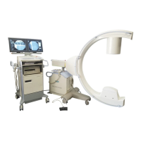
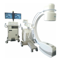
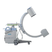
Do you have a question about the Siemens ARCADIS Varic and is the answer not in the manual?

Siemens ARCADIS Varic Specifications

General IconGeneral
TypeMobile C-arm
Image Intensifier9-inch or 12-inch
DICOM CompatibilityYes
Frame RateUp to 30 fps
Focal Spot Size0.3/0.6 mm
MonitorDual 18-inch TFT LCD monitors

Summary

ARCADIS System Manual

ON/OFF Assembly Replacement Instructions

Detailed instructions for replacing the ON/OFF assembly on ARCADIS systems.

General Information and Safety

Notes and Safety Symbols

Explains safety alert symbols like DANGER, WARNING, CAUTION, NOTICE.

Validity of Instructions

Defines the applicability of instructions to specific system models and serial numbers.

General Safety Precautions

Covers general safety warnings, electrical, radiation, and mechanical hazards.

Infection Prevention and Grounding Tests

Details on infection risk, ground wire resistance, and leakage current testing.

Required Resources

Lists necessary documents, tools, and materials for the procedure.

Removing the ON/OFF Assembly

Accessing Internal Components

Steps to open the monitor trolley and gain access.

Disconnecting Relay and ON/OFF Assemblies

Procedures for removing the relay and main ON/OFF assemblies.

Installing the ON/OFF Assembly

Preparations and Wiring Overview

Initial setup, voltage setting, and wiring layout overview.

Cable Connections and Grounding

Connecting power, monitor trolley, and ground wires.

Internal Wiring and Terminal Connections

Wiring PS/2, adapter, D50, and X3 terminals.

System Startup, Tests, and Final Steps

Procedures for system boot-up, programming, ground wire test, and leakage current measurement.

ON/OFF Assembly Circuit Diagram

Provides a schematic extract of the ON/OFF assembly's circuit.

Changes to Previous Version

New Publication Information

Indicates this document is a new publication.

Related product manuals