Do you have a question about the Siemens ARCADIS Orbic and is the answer not in the manual?
Explains symbols and emphasized text used in the manual.
Specifies the scope and applicability of the replacement instructions.
Covers general safety, electrical safety, and warnings for severe injuries.
Details radiation hazards and mechanical safety precautions.
Addresses infection risks and procedures for ground wire resistance testing.
Provides information and procedures for measuring system leakage current.
Lists essential documents, tools, and materials for the task.
Steps to open the monitor trolley, including safety precautions.
Detailed steps for disconnecting and removing the relay assembly.
Procedures for loosening screws, disconnecting cables, and removing the assembly.
Setting the assembly to local voltage and checking fuses before installation.
Presents the wiring layout diagram for the D50 component.
Instructions for connecting power, monitor trolley cables, and ground wire.
Details replacement of PS/2 cable and wiring of adapter cable D50.X12-X22.
Specific instructions for plugging in various connectors to D50.
Wiring terminals D50, X3 and inserting the ON/OFF assembly.
Procedure for checking ground wire connections and resistance.
Instructions for connecting the power input and output plugs to the UPS.
Steps for system startup and programming parameters like grace period.
Performing operational checks after installation and startup.
Closing covers, performing final ground wire test, and documentation.
Performing and documenting system leakage current measurement.
Provides a detailed circuit diagram extract for the ON/OFF assembly.
Indicates that this is a new publication with no prior versions.
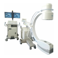
This document outlines the replacement instructions for the ON/OFF Assembly, material number 80 81 932, used in ARCADIS Varic systems (material number 80 80 017 up to serial number 10316) and ARCADIS Orbic systems (material number 80 81 080 up to serial number 20085). It serves as a system manual for maintenance and repair personnel.
The ON/OFF Assembly is a critical component responsible for controlling the power supply to the ARCADIS system. It integrates various power connections and control signals necessary for the system's operation, including connections for the main power cable, monitor trolley cable, PC (imaging system), and an optional uninterruptible power supply (UPS). This assembly manages the power flow to different parts of the system, ensuring proper startup and shutdown sequences. It also incorporates safety features such as fuses (F1 and F2) that are crucial for protecting the system from overcurrents, with specific fuse values dependent on the local mains voltage (e.g., 15 A for 200-240 V AC and 20 A for 100-127 V AC). The assembly also handles communication signals, such as the CAN cable for 3D Reconstruction options and PS/2 cable connections.
The ON/OFF Assembly facilitates the basic operation of the ARCADIS system by providing the means to switch it on and off. Its design ensures that power is distributed correctly to all connected components, including the monitor, PC, and other peripherals. The system's startup sequence involves connecting the monitor trolley with the C-arm chassis, plugging in the power, and then switching on the system. The assembly supports a "Power Off Grace Period" parameter, which can be programmed (e.g., to 15 seconds) to allow for a controlled shutdown of the PC (imaging processor) after the C-arm chassis is switched off. This feature ensures data integrity and prevents abrupt power loss to critical components. The assembly's integration with the UPS ensures continuous operation in case of power fluctuations or outages, with specific wiring for UPS input and output power cables.
Maintenance of the ON/OFF Assembly primarily involves its replacement and subsequent verification procedures. The instructions detail the steps for safely removing the old assembly, which includes de-energizing the system, disconnecting power plugs (including those for the UPS), removing various covers, and carefully detaching all connected cables and ground wires. Due to its weight, lifting the assembly requires two persons.
Installation of a new ON/OFF Assembly involves several key steps:
The document stresses the importance of observing all safety information, including general electrical safety, radiation safety, and mechanical safety, to prevent injuries, death, or material damage during maintenance procedures. ESD regulations must also be observed when working on the system.
| Brand | Siemens |
|---|---|
| Model | ARCADIS Orbic |
| Category | Medical Equipment |
| Language | English |