Document No. 570-136
Installation Instructions
October 26, 2016
Siemens Industry, Inc. Page 7 of 11
Each 4-20 mA sensor requires
a SEPARATE dedicated power
limited 24 VDC power supply.
DO NOT use the same
transformer to power both the
sensor and the controller.
Chaque capteur 4-20 mA
nécessite un source
d’alimentation SÉPARÉE
limitée à 24 VDC.
NE PAS utiliser le même
transformateur pour alimenter le
capteur et le contrôleur.
NOTE:
If the voltage/current switch is set to
current and a 4 to 20 mA sensor is
connected to an AI, then special wiring
requirements must be followed.
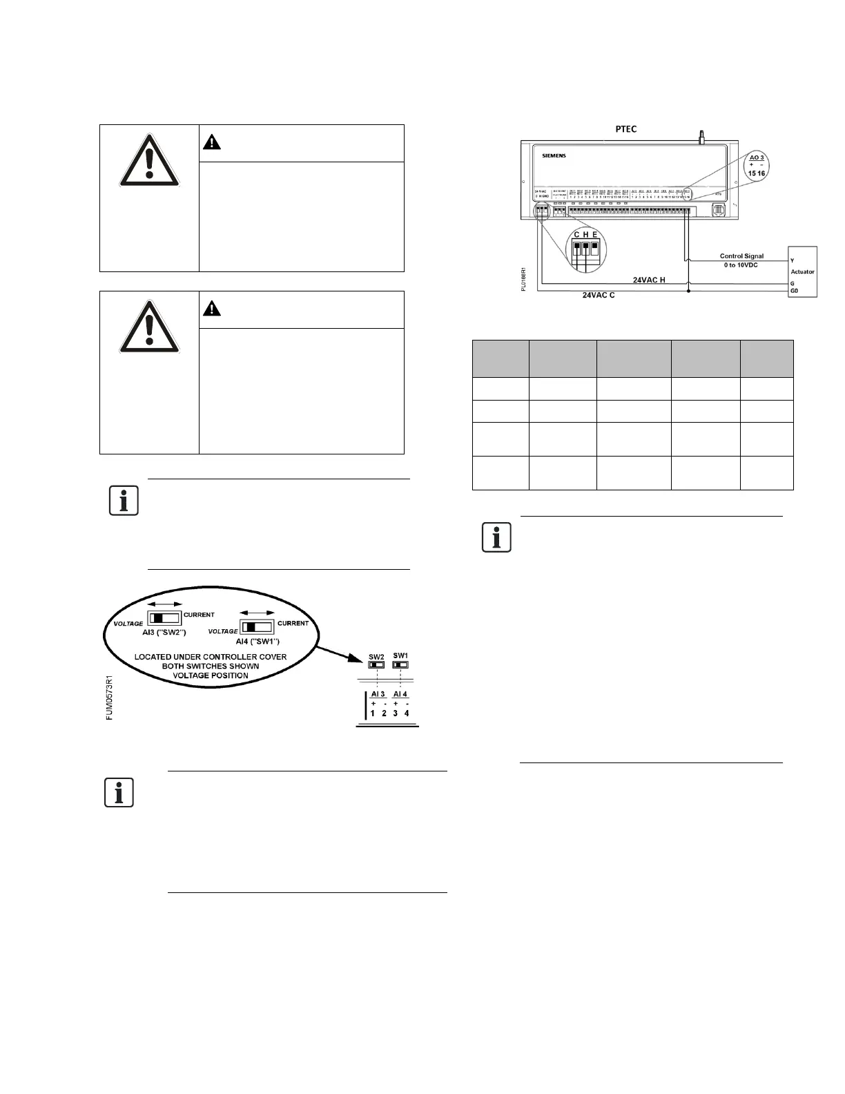
NOTE:
When wiring any actuator that uses a 0 to
10V control signal and ties AC neutral to DC
common, an additional wire must connect
the actuator AC neutral to the DC common
of the PTEC/TEC AO being used to control
the actuator.
24 Vac Modulating Control.
NOTE:
The controller’s DOs control 24 Vac
loads only. The maximum rating is 12 VA
for each DO. An external interposing
relay is required for any of the following:
• VA requirements higher than the
maximum
• 110 or 220 Vac requirements
• DC power requirements
• Separate transformers used to power
the load
(for example, part number 540-147,
Terminal Equipment Controller Relay
Module)
 Loading...