0DLQWHQDQFH
S7-300 Automation System, Hardware and Installation: CPU 31xC and CPU 31x
A5E00105492-03
10-5
5HPRYLQJDPRGXOH60)0&3
Remove the module as follows:
6WHS SLQIURQWFRQQHFWRU SLQIURQWFRQQHFWRU
1. Switch the CPU to STOP.
2. Switch off the load voltage to the module.
3. Remove the labeling strip from the module.
4. Open the front panel.
Unlock the front connector and remove it. 5.
Press down the unlocking
mechanism with one hand and with
the other hand, pull out the front
connector at the grips.
Remove the fixing screw from the middle
of the front connector. Pull the front
connector out, holding it at the grips.
6. Undo the module fixing screw(s).
7. Swing the module out.
CPU
PS
1
2
3
4
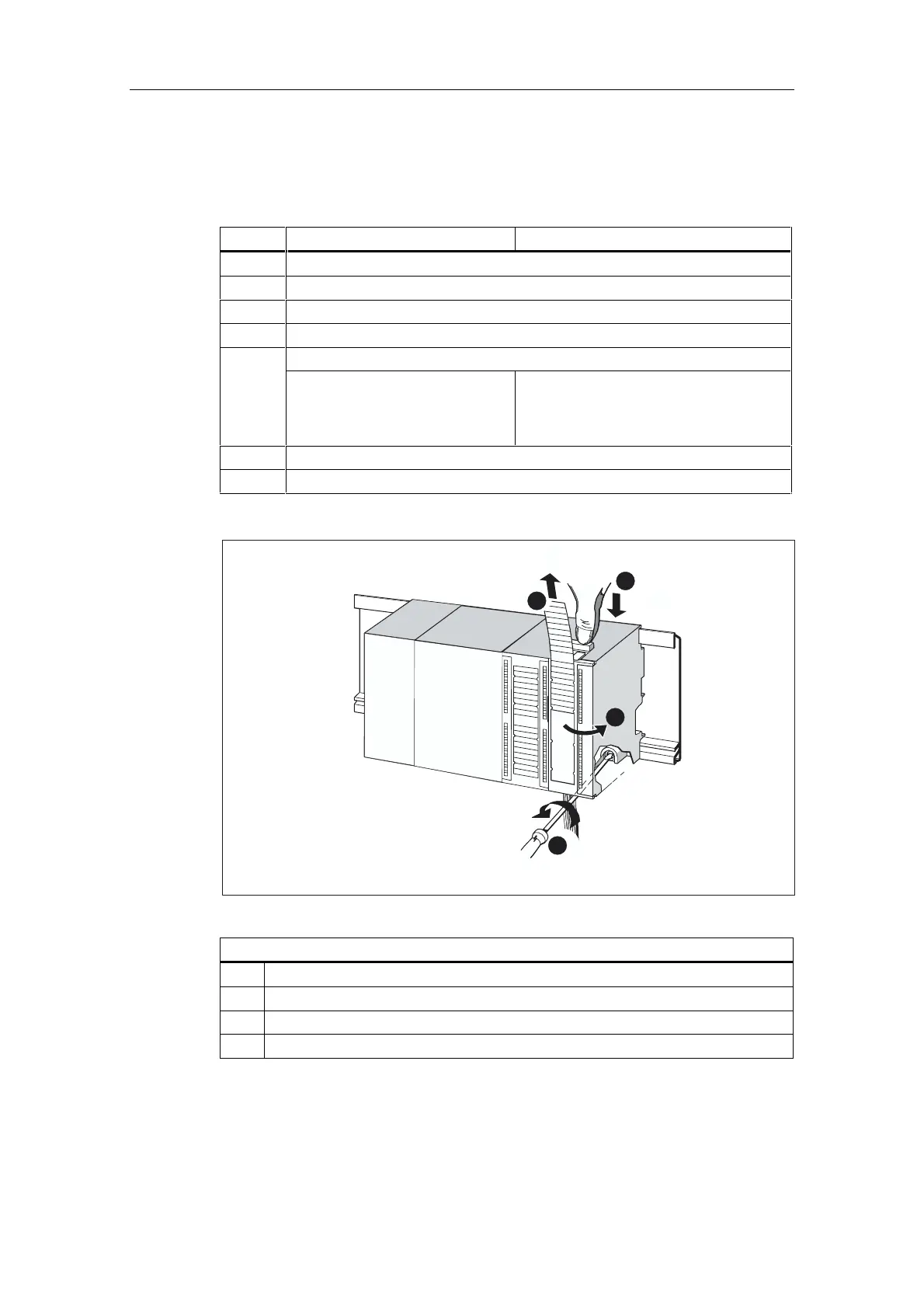
Figure 10-1 Unlocking the front connector and removing the module
7KLVILJXUHLOOXVWUDWHVWKHVWHSVGHVFULEHG
Remove labeling strips.
Open module.
Press unlocking mechanism/loosen mounting screw, and pull out front connector.
Remove mounting screw of module and tilt module out.
 Loading...