Do you have a question about the Siemens DI-3 and is the answer not in the manual?
Use 30-foot spacing as a guide, considering ideal conditions and specific applications.
Avoid locations with high humidity, dust, steam, or exhaust fumes to prevent false alarms.
Consider air currents from diffusers, windows, and doors affecting smoke detection.
Account for ceiling height, especially in large spaces, for smoke travel distance.
Account for beams, joists, and ducts that may alter smoke and air movement.
Detectors operate between 0-37.8°C and up to 93% humidity (non-condensing).
Lower air pressure at higher altitudes may affect ionization detector sensitivity.
Details on model suitability for open areas, computer facilities, and air ducts based on velocity and altitude.
Requires closer spacing and tiered locations based on stock, height, and judgment.
DI-3IS is for Class I, Division 1 areas; requires specific barriers or isolators.
Detectors connect per diagrams; follow panel wiring instructions and check detector limits.
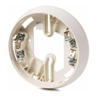
Route wires, position LED mark, mount base, and make terminal connections.
Ensure loop continuity after base installation, using a jumper for testing.
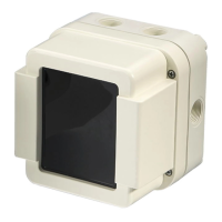
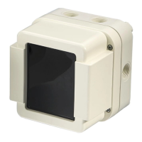
Align notch, push head into base, and twist clockwise to engage connections.
Push head up and rotate counterclockwise to disengage from the base.
Field adjustable for DI-3/DI-3H/DI-3IS; adjust towards '+' for increased sensitivity.
DI-A3 and DI-A3H detectors have factory-set sensitivity and are not field adjustable.
Use Model TM-13 tester via sensitivity jack for testing within factory limits.
Use SIEMENS Test Gas P/N 315-282747 for GO/NO GO operation testing.
Gently brush or vacuum slots; disconnect power before cleaning if using suction.
Adjust sensitivity; replace head if outside limits. Do not disassemble detectors.
Lists compatible control equipment for DI-3, DI-3H, DI-A3, and DI-A3H models.
Lists compatible control equipment for DI-3IS FM Approved model.
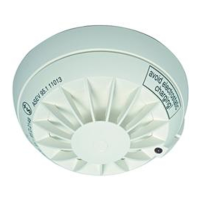
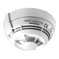
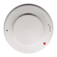
This document provides installation and wiring instructions for Siemens Smoke and Fire Detector Models DI-3, DI-3H, DI-3IS*, DI-A3, and DI-A3H. These instructions adhere to the installation guidelines of NFPA 72, National Fire Alarm Code, and CAN/ULC-S524, The Installation of Fire Alarm Systems.
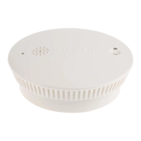
These detectors are designed to sense smoke and fire conditions within a protected area. They integrate into a compatible control unit to provide early warning of potential fire events. The DI-3IS model is specifically FM approved for intrinsically safe applications.
Detector Placement: While no specific spacings are allocated for these detectors in clean air velocity applications (0 to 300 ft/min), a 30-foot center spacing (900 sq ft) from NFPA Standard 72 Chapter 5 and CAN/ULC-S524 is a practical guide. However, actual protected area may be less due to ideal conditions not always being met (e.g., smooth ceiling, no air movement, physical obstructions). It is crucial to follow installation drawings provided or approved by Siemens Industry, Inc. Detectors should be located on the ceiling, a minimum of 6 inches from a side wall, or on a wall, 6 inches from the ceiling, except in special circumstances like computer room underfloors where velocity may be between 300 and 1200 ft/min.
Special Ceiling Construction Factors: Ceiling obstructions significantly impact smoke and fire product movement. Obstructions like beams, joists, and ducts can create "dead air" spaces or channel smoke, affecting detector placement. For detailed guidance, refer to the Initiating Devices chapter of NFPA Standard 72 for specific construction types (e.g., beam, suspended, level, sloped, and peaked ceilings).
Air Currents: Air movement significantly influences how smoke and fire products travel. Detectors should be placed to intercept these products before they dissipate. Consideration must be given to windows, doors, and HVAC systems. Detectors should not be installed in the air stream of a room air supply diffuser if it may advantageously position the detector closer to an air return.
Pressure: Normal changes in atmospheric pressure have a negligible effect on detector sensitivity. However, lower air pressure at higher altitudes does have some effect on the sensitivity of ionization type detectors.
To Avoid Nuisance Alarms:
Detector Wiring: Siemens Industry, Inc. detectors are interconnected as shown in Figure 1. Wiring should be done according to the Wiring Connection drawing, the control panel manual, and the installation manual. Ensure proper documentation and adherence to the maximum number of detectors permitted per circuit.
Detector Mounting: The detector is provided with a separate base which attaches to a standard 4-inch square, 4-inch octagonal, or single gang electrical box. The depth of the box is determined by the National Electrical Code for the number and size of the conductors used.
Installation of Detector Head:
Detector Sensitivity: The normal sensitivity range is found on the back of the detector. A decrease in sensitivity indicates the detector needs cleaning, ambient conditions have changed, or the detector is faulty.
Testing: Testing should be performed by qualified personnel. Use a sensitivity jack test to directly measure detector sensitivity in its mounted position while powered by the system. Access the sensitivity test jack through five holes on the front face of the detector (See Figure 4). Use sensitivity tester Model TM-13 (P/N 315-086641). Test frequency should be in accordance with NFPA Standard 72. For GO/NO GO operation, use Siemens Test Gas, P/N 315-282747, following label instructions.
Cleaning: Dust accumulation can shift detector sensitivity. Periodic checks and light cleaning are necessary. The minimum test schedule can be found in NFPA 72, Chapter 7 (U.S.) and CAN/ULC-S537 (Canada). Cleaning intervals should be tailored to the individual detector environment. Clean by lightly brushing all open slots. Vacuum cleaning is also possible, but power should be disconnected to prevent alarms.
Repair: Detectors are not designed for thorough cleaning in the field. If sensitivity falls outside acceptable limits and cannot be adjusted back (where applicable), replace the detector head. Send removed heads to the nearest Siemens Industry, Inc. Authorized Service Center for servicing. CAUTION: Under no circumstances should the detector head be disassembled. No field repairs should be attempted. Detectors are factory repairable only.
| Brand | Siemens |
|---|---|
| Model | DI-3 |
| Category | Smoke Alarm |
| Language | English |