008335_e_--_--
Building Technologies
2014-04-17 Control Products and Systems
Linearer Rauchmelder DLO1191
Justierset FDLU291
Inbetriebnahme
Linear smoke detector DLO1191
Adjustment tester FDLU291
Commissioning
Verwendungszweck
Der Lineare Rauchmelder detektiert den Rauch und
eignet sich für die Brandüberwachung in grossen Lager-
und Fabrikationshallen auch mit komplexen Deckenkon-
struktionen.
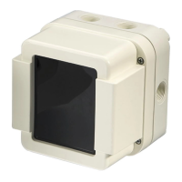
Er besteht aus dem eigentlichen Melder und
einem Reflektor, der dem Melder gegenüberliegend
angeordnet ist.
Intended use
The linear smoke detector detects smoke and is suited
for fire detection in large storage and factory halls, also
with complex ceiling constructions. It consists of the d
e-
tector itself and a reflector placed opposite the detector.
Der Lineare Rauchmelder fällt gemäß EN 62471 'Photo-
biologische Sicherheit von Lampen und Lampensyste-
men' in die risikofreie Gruppe (englisch: 'Exempt Group').
In accordance with EN 62471, 'Photobioligical Safety of
Lamps and Lamp Systems', the linear smoke detector falls
into the 'Exempt Group'.
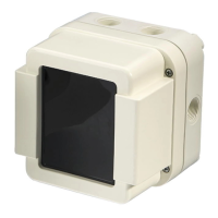
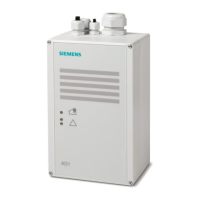
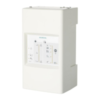
Aufbau und Funktion des Justiersets
Die Inbetriebnahme erfolgt mit Hilfe eines Justiersets,
das aus einem Justiergerät, Alarmtest-Filter, Magneten,
der Zielvorrichtung, und Verbindungskabeln besteht.
Das Justiergerät erkennt automatisch den zuletzt im
Melder gespeicherten Entfernungsbereich (Range) und
das aktuelle Signal.
Die schrittweise Bedienung des Justiergerätes während
der Inbetriebnahme erfolgt über die rechte Taste unter-
halb des Displays.
Die Beleuchtung des Displays kann über die linke Taste
aktiviert werden.
Bei Nichtbenutzung schaltet sich das Justiergerät nach
5 Minuten automatisch aus.
Das Justiergerät wird mit einer 9-Volt-
die auf dessen Rückseite in einem Schacht unterge-
bracht ist.
Setup and function of the adjustment set
Commissioning is ensured by means of an adjustment
set consisting of an adjustment device, alarm test filter,
magnets, the sighting system and connection cables.
The adjustment device automatically detects the last
detection range stored in the detector and the current
signal.
The step-by-step operation of the adjustment device
during commissioning is ensured by the right button be-
low the display.
The display illumination can be activated by pressing the
left button.
When not used, the adjustment device will switch off
automatically after 5 minutes.
The adjustment device is operated with a 9V battery
located in a shaft at the back of the device.