These instructions are written in accordance with
the installation guidelines of NFPA No. 72, National
Fire Alarm Code, and CAN/ULC-S524, The
Installation of Fire Alarm Systems.
DETECTOR PLACEMENT
For a clear air, 0 to 4000 ft/min velocity applica-
tion, use 30 foot center spacing (900 sq ft) from
NFPA Standard 72 Chapter 5 and CAN/ULC-S524
as a starting point for a detector installation layout.
This spacing, however, is based on ideal conditions –
smooth ceiling, no air movement, and no physical
obstructions. In some applications, considerably
less area is protected adequately by each smoke
detector. In all installations, place the detector on
the ceiling, a minimum of 6 inches from a side wall,
or on a wall, 6 inches from the ceiling.
Follow the drawings provided or approved by
Siemens Building Technologies, Inc. or by its
authorized distributors.
See NFPA 72, National Fire
Alarm Code, Chapter 5 for additional guidance on
special issues such as beamed construction and high
stockpiling.
TO AVOID NUISANCE ALARMS:
DO NOT locate the PE-11C/PE-11T detector where
excessive smoke concentrations exist under
normal conditions, or in areas of prolonged high
relative humidity where condensation occurs.
DO NOT locate the PE-11C/PE-11T detector next
to an oil burner, kitchen, or garage where exhaust
fumes can trigger an alarm. Other causes of false
alarms are dust accumulation, heavy
concentrations of steam, heavy pipe or cigar
smoke, and certain aerosol sprays.
AIR CURRENTS
Before a detector can sense a fire, the products of
combustion or smoke must travel from the fire to the
detector. Since their travel is especially influenced
by air currents, consider the movement of air in the
design of the system.
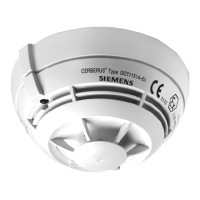
Installation/Wiring Instructions
Models PE-11C/PE-11T
Siemens Building Technologies
Fire Safety
P/N 315-095626-6
While combustion products tend to rise, drafts from
hallways, air diffusers, fans, etc., may help or hinder
the travel of combustion products to the detector.
When positioning a detector at a particular location,
give consideration to windows and doors, both open
and closed, and to influencing air movement. Never
install a detector in the air stream of a room air supply
diffuser. It is better to position a detector closer to an
air return.
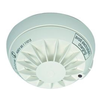
SPECIFICATIONS
Environmental
Temperature: 32
0
F (0
0
C) to 100
0
F (38
0
C).
Humidity: Up to 93% RH, non condensing
Air Pressure: No effect.
Thermal Alarm Temp.: 135
0
F (57
0
C)
Electrical
Voltage: 16-27 VDC
Ripple: 3V peak-to-peak
Supervisory Current: 110µA max
Alarm Current: 33-50mA
Start-up Time: 50 seconds max
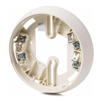
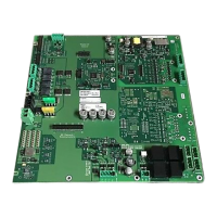
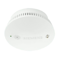
DETECTOR WIRING
The PE-11C/PE-11T should be connected as shown
in Figure 1 using the separate mounting base, Model
DB-11. Follow the control panel wiring connection
drawing installed on the inside face of each control
panel cover. See DB-11 instruction, P/N 315-094193,
for base mounting.
Duplicate wiring information is also
in the Installation, Operation, and Maintenance Manual
provided
with every control panel
.
Note any
limitations on t
he number of detectors and
restrictions on the use of remote devices
permitted for each circuit.
INSTALLATION / REMOVAL OF DETECTOR
TO INSTALL:
• Align LED in detector with LED symbol on base
and insert detector into base.
• Rotate detector counterclockwise while gently
pressing on it until the detector drops fully into
base.