Do you have a question about the Siemens OP921 and is the answer not in the manual?
Provides guidance on placing smoke detectors for optimal coverage, considering ceiling conditions and obstructions.
Instructions on preventing false alarms by avoiding locations with excessive smoke or high humidity.
Explains how air currents affect smoke detection and placement considerations.
Discusses how ceiling features like beams affect smoke movement and detector placement.
Details the operational temperature, humidity, and air velocity ranges for the detector.
Explains the meaning of different LED colors and flash intervals for detector status.
Describes how to program detector addresses and select parameter sets.
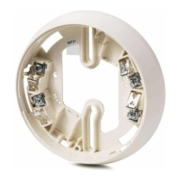
Provides instructions for installing and removing the detector head from its base.
Illustrates polarity insensitive and isolator mode wiring diagrams for the detector.
Outlines how to perform functional tests using approved smoke test gases.
Covers maintenance, disassembly warnings, and the prohibition of painting the detector.
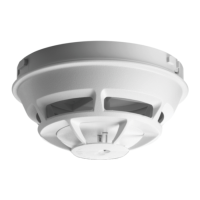
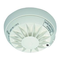
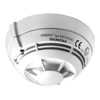
The Siemens Model OP921 is a photoelectric detector designed for fire alarm systems, compliant with NFPA 72 and CAN/ULC-S524 standards. It is UL268 7th edition listed, indicating its suitability for reducing nuisance alarms, particularly those caused by cooking.
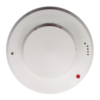
The OP921 detector operates by sensing smoke in its sensing chamber. It continuously monitors smoke sensitivity to ensure it remains within rated limits and also checks its internal sensors and electronics. This microprocessor-based detector provides visual feedback through an LED indicator that can flash in three distinct colors: green, yellow, or red, each signifying a different operational status.
The detector supports two operational modes: polarity insensitive mode and isolator mode. In isolator mode, built-in dual isolators work on both sides of the detector to isolate line shorts in front of or behind the device. This feature enhances system reliability by preventing a single fault from affecting the entire loop.
Proper placement is crucial for optimal performance. While no specific spacings are set for clean air applications, NFPA 72 and CAN/ULC-S524 suggest a 30-foot center spacing (900 sq ft) as a guide. However, actual protected area can be significantly less depending on environmental factors. Detectors should always be placed on the ceiling, a minimum of 6 inches from a side wall, or on a wall, 12 inches from the ceiling. For ideal smooth ceiling conditions, detectors can be placed at a maximum center spacing of 50 feet (2500 square feet).
The installation process requires careful consideration of factors such as air currents, temperature, humidity, pressure, fire load, room configuration, and ceiling type (sloped, flat, smooth, or beamed). Siemens Industry, Inc. emphasizes adherence to installation drawings, which are developed based on extensive experience to ensure optimal detector placement. Sound engineering judgment by qualified personnel is essential.
To prevent false alarms, the detector should not be located in areas with excessive smoke concentrations under normal conditions, prolonged high relative humidity causing condensation, near oil burners, or in garages where exhaust fumes could trigger an alarm. Other common causes of false alarms include dust accumulation, heavy steam concentrations, and certain aerosol sprays.
Air currents significantly influence how combustion products or smoke travel to the detector. When designing the system, it's important to consider air movement from windows, doors (both open and closed), and ventilating systems. Detectors should not be installed in the air stream of a room air supply diffuser; positioning them closer to an air return is preferable. While combustion products tend to rise, drafts can either aid or hinder their travel. Average ceiling heights (8 to 10 feet) typically do not affect detector response, but high ceilings in large spaces like churches or warehouses require special consideration.
Ceiling obstructions such as girders, joists, beams, and air conditioning ducts can alter air and smoke movement. These elements can slow heated air and smoke movement or create pockets with reduced smoke levels. Architectural design must be factored into area protection. Refer to NFPA Standard 72 for specific location and spacing requirements for various construction types (e.g., beam, suspended, level, sloped, and peaked ceilings). The detector is also compatible with the STI-9604 mechanical protection guard.
For polarity insensitive mode, Line -6 and -5 can be either line of the loop. In isolator mode, the positive line must connect to 1b and the negative line to 6. The next device in the loop should connect to 1b and 5. The line isolator is situated between connector 6 and 5. It is crucial to ensure the control panel supports isolator mode for the specific product version of the OP921 (version 17 or higher). Isolator mode should not be used with OP921 product versions below 17. Wire size should be a maximum of 14 AWG and a minimum of 18 AWG; wires larger than 14 AWG can damage the connector.
To ensure proper installation, wires should be dressed flat against the base, slack taken up in the outlet box, and wires routed away from connector terminals. To install the detector head, rotate it counterclockwise while gently pressing until it seats fully into the base, then rotate clockwise until it stops and locks. An optional locking screw (Model LK-11) can be inserted. To remove, loosen the locking screw (if installed), rotate counterclockwise until it stops, and pull it out of the base.
Each detector must be programmed with an address between 001 and 252 using the Model DPU Device Programming Unit. The loop and device number (system address) should be recorded on the detector label and base to prevent incorrect installation. The optional DPU label printer can assist with this. Detectors offer pre-programmed parameter sets selectable by the panel, including "Standard" and "Duct." For direct in-air duct applications, the detector must be set to the "Duct" parameter.
A functional (Go, No-Go) test should be performed using approved test gases such as Smoke Sabre, Smoke Centurion, Solo A5 Smoke Detector Tester Gas, Solo A10, Testifire 1001/2001, HSI PurCheck, or HSI SmokeCheck™. This test verifies that smoke can enter the sensing chamber and trigger an alarm at the programmed obscuration level. The OP921 detectors can also be individually tested using the DPU.
The control unit automatically signals a trouble message if the OP921 detector's smoke chamber changes to a level where the set sensitivity cannot be maintained. In such cases, the detector may require replacement.
The sensitivity of OP921 detectors can be individually tested using the DPU. The sensitivity can also be measured by the control panel, following its specific instructions.
Only qualified service personnel should perform testing. Both sensitivity and functional tests must be conducted to ensure proper operation. The minimum test schedule can be found in the current edition of NFPA 72.
| Model | OP921 |
|---|---|
| Manufacturer | Siemens |
| Protection Class | IP40 |
| Type | Optical |
| Relative Humidity | ≤ 95 % rel. humidity |