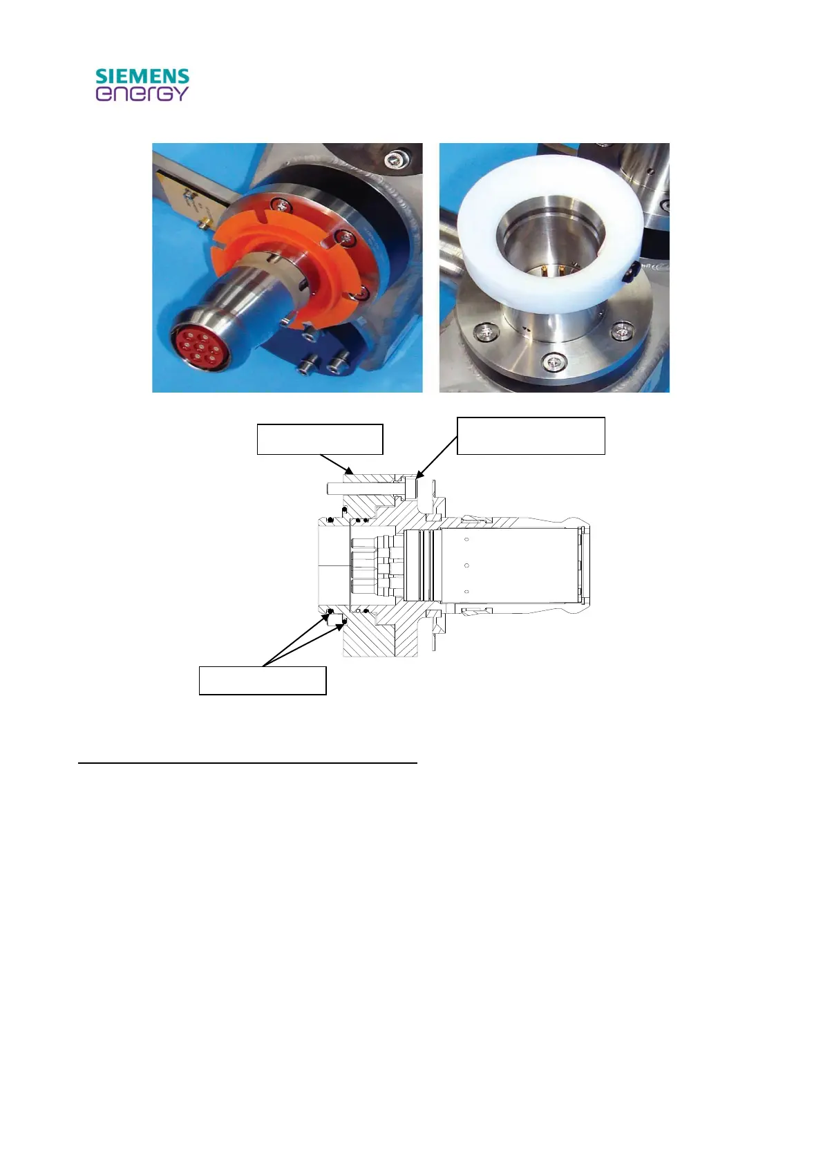
Figure 11 Typical bulkhead ROV connectors
Figure 12 ROV bulkhead connector sectional view
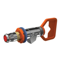
Installation of compliant flange mounted connector
Refer to Figure 13 for a typical flange-mounted ROV connector, and Figure 14 for installation
diagram.
Remove M6 mounting screws and orientation disc, pass the front of the connector through the
interface, install 4 off M6 mounting screws and orientation disc, secure screws with a spot of Loctite
243 on the threads and torque to 10-12 Nm (7.38 – 8.85 lbf.ft).: