Do you have a question about the Siemens DLC and is the answer not in the manual?
| Brand | Siemens |
|---|---|
| Model | DLC |
| Category | Recording Equipment |
| Language | English |
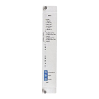
Description of the Model DLC Device Loop Card from Siemens Industry, Inc., its purpose, and system integration.
Details on how the DLC initializes, operates, maintains devices, and communicates information to the System CPU.
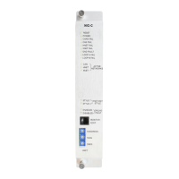
Description of the green POWER LED indicating power applied to the DLC card.
Description of the yellow CARD FAIL LED indicating a microprocessor failure.
Description of the yellow HNET FAIL LED indicating communication termination.
Description of the yellow GND FAULT LED indicating a ground fault detection.
Description of the red ALARM LED indicating an alarm condition detected by the DLC.
Description of the yellow TROUBLE LED indicating a field wiring or firmware incompatibility issue.
Indicators for Zone 1 wiring faults: Class A Open, Class A Return, and Short.
Indicators for Zone 2 wiring faults: Class A Open, Class A Return, and Short.
Instructions for setting the three-digit HNET network address using rotary dial switches.
Step-by-step guide for physically inserting the DLC card into the CC-5 card cage.
Safety warning to remove system power before installation and wiring.
Procedure for connecting field wiring to the terminal blocks of the CC-5 card cage slot.
Instructions for connecting +24V and -24V from the PSC-12 to the DLC slot.
Lists compatible devices for UL 864 and UL 2572, including model numbers.
Details on loop capacity, device limits per zone, and total devices supported.
Information on wire type, conduit, T-tapping rules for Class A loops, and UL/ULC listing.
Specifies power limits, wire resistance, and capacitance limits for the circuits.
Notes on multi-criteria detector programming and compliance with standards.
Emphasizes the necessity of a comprehensive, customized security concept for system operation.




 Loading...