Siemens Industry, Inc. A6V10337045_en--_n
Smart Infrastructure
Remote Connectivity
The FC2025/2050 and FV2025/2050 can send events via the Connect X300 gateway for remote diagnostics and
serviceability. The Connect X300 can be installed as a node on the FCnet or FVnet.
Installation
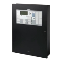
The FC2025, FC2050, FT2050,FV2025, FV2050 and VR2005 panels are installed in dry, protected environmentsusing
different enclosures that consist of backbox, inner door and outer door that is lock-protected and have clear plexiglass
windows. The FV2025 and FV2050 panels use 3-Height enclosure units; the FC2025 and FC2050 panel use 2-Height
enclosure units and the FT2050 and VR2005 use 1-Height enclosure units. All the modules are installed inside the
enclosure backbox and inner doors (refer to Figure 3). An optional DIN Rail Kit is available (PN: S54400-B44-A1) to allow
indirect wiring connection to the PMI and other modules that support low power field wiring. An optional Battery Seismic
Kit is available (PN: S54400-B43-A1 or S54400-B55-A1) to meet the seismic requirement. An optional Battery Disconnect
module (S54400-B145-A1) is available to meet ULC requirements. An optional Ethernet Switch Module (S54400-B152-
A1) is available to allow the FC2025/FC2050/FT2050 panels to be networked with FV2025/FV2050.
To support migration from legacy installations, the use of the FHA2056-U1/-R1 is recommended (PN: S54400-B18-A1
[Black] or S54400-B19-A1 [Red]).
For complete module mounting and installation, please refer to the FS20 Mounting, Installation and Product Data manual,
Document ID A6V10315015.
Wiring
For FS20 System wiring, refer to the applicable module section of theFS20 Mounting, Installation and Product Data
manual, Document ID A6V10315015,and module installation instructions.
External FS20 System Wiring
FCNET – Refers to communication connection between panels using SafeDLink module (S54400-A60-A1) and/or Fiber
network modules (SM/MM) (FN2006-U1 / FN2007-U1). This can be configured as Class A and B and is supervised. Refer
to the FS20 Mounting, Installation and Product Data manual, Document ID A6V10315015, for proper wiring connection.
RS485 Remote Peripheral (UFP) – connection of the FACP to the Remote display (FT2014-U2, FT2014-R2), Remote
terminal (FT2015-U2, FT2015-R2), Remote peripheral module (FCA2018-U1), LED annunciator driver (FT2007-U1),
Tabular annunciator 16 zone (FT2008-U1/FT2008-R1), Tabular annunciator 32 zone (FT2009-U1/FT2009-R1), and
Graphic driver (I/O) (FT2003-U1) through the RS485 class A module (isol.) (FCA2016-A1). This can be configured as
Class A and B and is supervised. Refer to theFS20 Mounting, Installation and Product Data manual, Document ID
A6V10315015, for proper wiring connection.
FDNET – Signaling Line Circuits (SLC) that used P2 proprietary protocol connection of the FACP to the Initiating Devices
such as Detectors, Monitor switches, etc., through the Periphery board (250p/500p) (FCI2016-U1/FCI2017-U1). This can
be configured as Class A, B, or X and is supervised. Refer to the FS20 Mounting, Installation and Product Data manual,
Document ID A6V10315015, Section 25, for proper wiring connection and compatible devices. A full portfolio of peripheral
devices with optional built-in isolation including the PAD-5 is available for use on the FDNET.
Notification Appliance Circuit (NAC) –This is the connection of FACP to the Notification Appliances devices through the
Periphery board (250p/500p) (FCI2016-U1/FCI2017-U1) or optional NAC Module (1A/2B) (FCI2011-U1). This can be
configured as Class A or Class B and issupervised. Refer to the FS20 Mounting, Installation and Product Data manual,
Document ID A6V10315015, for proper wiring connection, and Document ID A6V10333530 for List of Compatible NAC
Devices.
Releasing Circuit – This is the connection of the FACP to releasing devices such as solenoids and squibs through the
optional Releasing module (XCI2001-U1). This is configured as Class B or Class A and is supervised. The releasing
application meets the requirement for the following regulation: NFPA 13, NFPA 750, NFPA 2010, NFPA 2001.
Refer to the FS20 Mounting, Installation and Product Data manual, Document ID A6V10315015, Section 22, for proper
wiring connection. Refer to the Solenoid Compatibility List, Document ID A6V11620059.
VCNet Connections – Refers to the communication connection between Voice panels using Ethernet modules (VN2001-
A1, VN2002-A2, VN2003-A3). This can be configured as Class B or Class X and is supervised. Refer to the FS20
Mounting, Installation and Product Data manual, Document ID A6V10315015, for proper wiring connection.
 Loading...


