Annex technical data
9
Tones and sound levels of the interbase (DC 32 V)
36
Building Technologies A6V10320090_c_en_--
Fire Safety 02.11.2011
9 Annex technical data
9.1 Tones and sound levels of the interbase (DC 32 V)
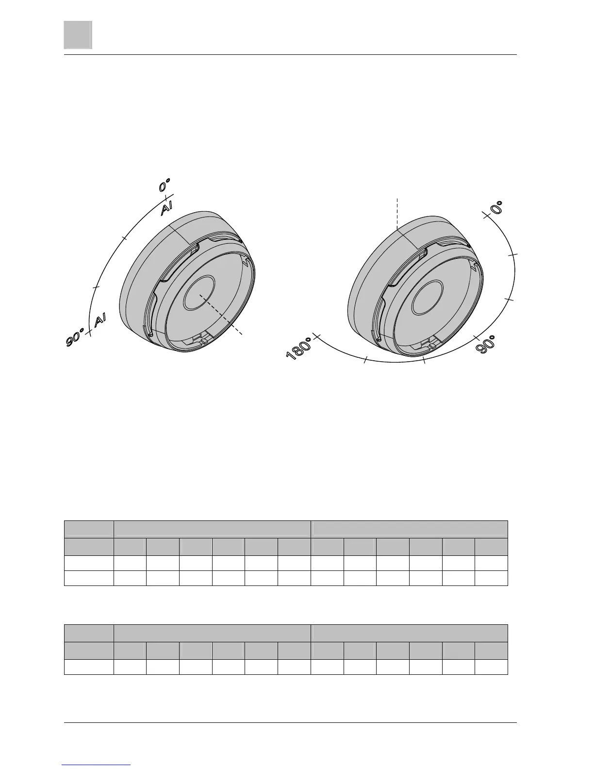
To indicate the effective sound level of the interbase FDSB229, a polar coordinate
system is used in accordance with EN 54-3, Annex A. The zero point (0°,0°) refers
to the position of the alarm indicator (AI) in an inserted point detector.
The direction of rotation from horizontal to vertical is counter-clockwise.
AI at 0°: Horizontal AI at 90°: Vertical
The measurements were performed with cover plate FDBZ296 fitted.
The tables below illustrate the beam characteristics at maximum sound level. All of
the sound levels specified are minimum values. For the tone no. 1 'Continuous', the
sound levels are also specified at a reduced sound level for information purposes.
Sound level measured in dBA/1 m (DC 32 V)
Tone No. 1: Continuous
Sound level Horizontal Vertical
15° 45° 75° 105° 135° 165° 15° 45° 75° 105° 135° 165°
0 (max.) 79 76 81 82 75 75 80 74 79 80 73 79
1 (mid.) 68 65 72 71 65 64 70 64 69 71 64 69
Tone No. 2: Intermittent
Sound level Horizontal Vertical
15° 45° 75° 105° 135° 165° 15° 45° 75° 105° 135° 165°
0 (max.) 74 74 81 81 74 75 78 77 78 80 75 77