Home
Siemens
Industrial Equipment
Flender KMP Series
Siemens Flender KMP Series User Manual
4
of 1
of 1 rating
84 pages
Give review
Manual
Specs
To Next Page
To Next Page
To Previous Page
To Previous Page
Loading...
16 / 84
BA 9142 en 02/2015
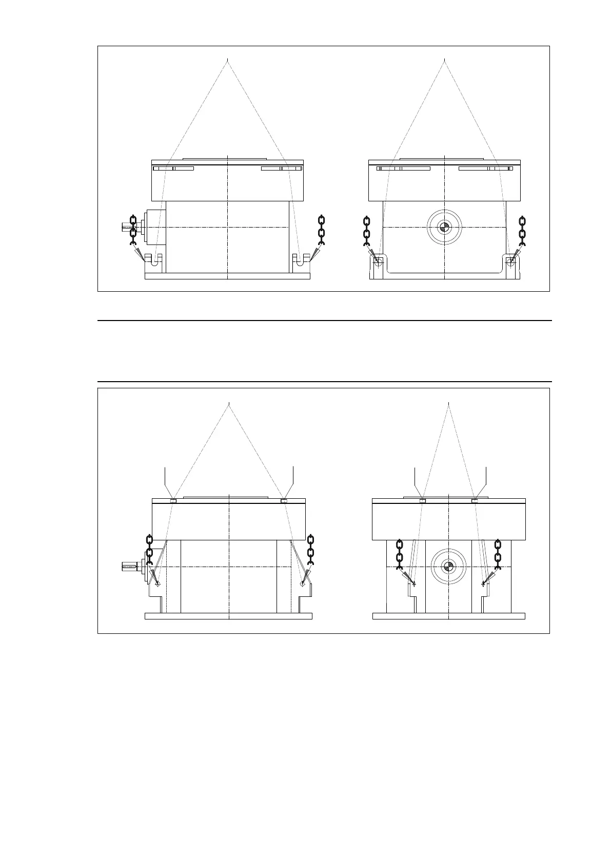
Fig. 3:
Attachment points
Note
If no transport lobes are provided on the base of the gear unit, the transport lobes that are marked on
the
fins have to be used. If no cable pulley is on the gear unit head, wooden blocks have to be used for
protection of the gear unit (see Figure 4).
1
1
1
1
Fig. 4:
Alternative attachment points
1
Wooden block
15
17
Table of Contents
Default Chapter
5
Table of Contents
5
1 Technical Data
8
General Technical Data
8
Measuring-Surface Sound Pressure Level
8
List of Equipment
8
2 General Notes
9
Introduction
9
Copyright
9
3 Safety Instructions
10
Obligations of the User
10
Special Dangers and Personal Protective Equipment
12
The Five Safety Rules
13
Environmental Protection
13
4 Transport and Storage
14
Content and Check of the Scope of Delivery
14
Transport
14
Storing the Gear Unit
17
Standard Coating and Corrosion Prevention
18
Exterior Preservation of Metallic Bright Exterior Surfaces
19
Maximum Durability Period of the Exterior Preservation
19
Prolongation of the Preservation of Metallic Bright Exterior Surfaces of the Gear Unit
19
Preservation of the Interior of the Gear Unit
19
Maximum Durability Period of the Interior Preservation of the Gear Unit
19
Combined Storage/Packaging
21
Renewal of the Interior Preservation of the Gear Unit for Longer Periods of Storage of the Gear Unit that Has Not Been Taken into Operation yet
25
Renewal of the Gear Unit Interior Preservation with "Castrol Corrosion Inhibitor N 213
25
Renewal of the Gear Unit Interior Preservation through Complete Filling with Preservative or Operating Oil
27
Renewal of the Interior Preservation of the Gear Unit Using the Oil-Supply System
29
5 Technical Description
31
General Description
31
Delivery Condition of the Gear Unit
31
Lubrication
32
Hydrodynamic Lubrication of the Axial Tilting Pad Thrust Bearings
32
Hydrodynamic Lubrication of the Axial Tilting Pad Thrust Bearings in Gear Units with Hydrostatic Start-Up Assistance
32
Hydrodynamic Lubrication of the Axial Tilting Pad Thrust Bearings with Radial Piston Pump
32
Labyrinth Seals
33
Drive Coupling
33
Heating
34
Indication of Oil Level
34
Oil Temperature Monitoring
35
6 Fitting
36
General Assembly Information
36
Set-Up Conditions
37
Dimensions and Weights
37
Lifting Device
37
Preparatory Measures for Gear Unit Installation
37
Maintaining Preservation if the Gear Unit Has Been Opened in the Meantime
39
Foundation
39
Assembly of the Gear Unit
39
Installing the Pipework
40
Pickling of Adapted Pipes
41
Installing the Couplings
41
Installing the Motor
42
Assembly of Loose Add-On Parts Included in the Delivery
43
Welding Work on the Mill
43
General Notes on Add-On Components
43
Final Work
44
Screw Connection Classes, Tightening Torques and Initial Stressing Forces
44
Screw Connection Classes
44
Tightening Torques and Initial Stressing Forces
45
7 Start-Up
47
Procedure before Start-Up
47
Removal of Preservative Agent from Exterior
47
Removal of Preservative Agent from Interior
48
Draining Preservative Oils
50
Flushing before Initial Start-Up
51
Oil Quantity for Flushing
51
Fill in Operating Oil
51
Oil Level
52
Procedure for Filling
52
Oil-Supply System
54
Checks before Start-Up
54
Start-Up
56
Pre-Lubrication Phase
56
Initial Start-Up
56
Checking Procedure
57
Removal from Service
57
Renewal of the Gear Unit Interior Preservation on Gear Units Having Already Been in Operation
58
Renewal of the Interior Preservation of the Gear Unit Using the Oil-Supply System
58
Renewal of the Gear Unit Interior Preservation with "Castrol Corrosion Inhibitor N 213
60
Renewal of the Gear Unit Interior Preservation through Complete Filling with Preservative or Operating Oil
62
Exterior Corrosion Prevention
63
8 Operation
64
General
64
Oil Level
65
Irregularities
65
9 Faults, Causes and Remedy
66
General Information on Faults and Malfunctions
66
Faults, Causes and Remedy
67
10 Maintenance and Repair
70
General Notes on Maintenance
70
Clean the Gear Unit
71
Clean the Air Filter
71
Replacing the Air Filter Cartridge
71
Flushing
72
Oil Filling
72
Inspection
73
Maintenance
74
Examine Water Content of Oil, Conduct Oil Analyses
75
Change Oil
76
Check Tightness of Screw Connections
78
Welding Work on the Mill
78
Vibration Measurements
79
Repair
80
General Inspection of the Gear Unit
81
Lubricants
81
11 Spare Parts, Customer Service
82
Stocking Spare Parts
82
Addresses for Ordering Spare Parts and Customer Service
82
12 Declarations
83
Declaration of Incorporation
83
4
Based on 1 rating
Ask a question
Give review
Questions and Answers:
Need help?
Do you have a question about the Siemens Flender KMP Series and is the answer not in the manual?
Ask a question
Siemens Flender KMP Series Specifications
General
Brand
Siemens
Model
Flender KMP Series
Category
Industrial Equipment
Language
English
Related product manuals
Siemens Flender KMPS Series
84 pages
Siemens Flender KMPP Series
84 pages
Siemens FLENDER K SH Series
109 pages
Siemens FLENDER T3SH
96 pages
Siemens FLENDER B3HH
96 pages
Siemens FLENDER B3SH
96 pages
Siemens FLENDER B3SE
96 pages
Siemens FLENDER B3DH
96 pages
Siemens FLENDER H1SH
96 pages
Siemens FLENDER B3 E Series
96 pages
Siemens FLENDER H SH Series
96 pages
FLENDER PLANUREX 2 PBUC Series
54 pages