Do you have a question about the Siemens FLENDER B3HH and is the answer not in the manual?
Defines the qualifications and training necessary for personnel handling the gear unit.
Explains technical data shown on the rating plate that determines the limits of correct use.
Details the ATEX identification marking for gear units designed according to Directive 94/9/EC.
Outlines user responsibilities for safe operation, maintenance, and adherence to instructions.
Highlights specific hazards like hot/cold surfaces and requires appropriate PPE for handling.
Details requirements for lifting equipment, handling, and packaging observations during transport.
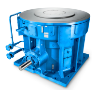
Describes the gear unit as a two or three-stage bevel-helical unit and its permissible inclinations.
Details the possible shaft configurations and how rotation direction is specified or realized.
Explains splash lubrication and pressure lubrication through add-on oil-supply systems.
Provides general guidance on fitting work, space requirements, and avoiding heat exposure.
Details foundation design, alignment, and fastening bolt requirements for installation on a housing base.
Outlines steps for cleaning, fitting drive elements, and ensuring ventilation during installation.
Details requirements for fitting the gear unit onto a foundation frame, ensuring horizontality and levelness.
Describes the process of fitting the gear unit on a concrete foundation using stone bolts or blocks.
Details fitting the gear unit on a concrete foundation using anchor bolts.
Details fitting procedures, including shaft cleaning, grease-free areas, and alignment.
Details the process of fitting the shrink disk, including cleaning, grease-free areas, and bolt tightening.
Provides instructions for removing the protective cover, undoing bolts, and drawing off the disk.
Covers checking screw connections, alignment, and refitting demounted devices.
Categorizes screw connections based on fastening type and specifies tightening procedures.
Provides detailed tables for initial-tensioning forces and tightening torques based on thread and strength class.
Instructs on removing preservative agent and identifying oil-draining points.
Details the process of filling the gear unit with fresh oil, including checks and oil quantity.
Details steps to perform before starting the gear unit, including oil draining and plug replacement.
Lists visual checks for explosion-protection marking, oil level, leaktightness, and rotating parts.
Specifies maximum permitted oil temperature and actions for exceeding it.
Advises on repair work during guarantee period and handling faults with unknown causes.
Provides a table listing common faults, their causes, and suggested remedies.
Emphasizes that maintenance must be done by trained personnel and lists general safety precautions.
Details specific maintenance tasks such as checking oil, cleaning filters, and inspecting components.
| Brand | Siemens |
|---|---|
| Model | FLENDER B3HH |
| Category | Industrial Equipment |
| Language | English |


