Building Technologies 74 319 0617 0 a 17.04.2008 28/180
en
Connection diagrams
A6 Room unit LPB Data bus (Local Process Bus)
B1 Flow or boiler temperature sensor M1 Heating circuit or boiler pump
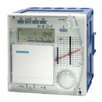
B5 Room temperature sensor N1 Controller RVL480
B7 Return temperature sensor (primary circuit) S1 Remote control operating mode
B71 Return temperature sensor (secondary circuit) S2 Remote control flow temperature setpoint
B9 Outside sensor Ux Heat demand output
E1 Two-stage burner
F1 Thermal reset limit thermostat
Y1 Actuator of heating circuit (with contact for minimum
stroke limitation)
F2 Manual reset safety limit thermostat * Wire link for locking the district heat parameters
Basic connections on the low voltage side
AC 230 V
B9
D2
LDBMB A6MD
B1
M
N
LPB
D1
MBMB
A6 B9
B1
B7 B5
M
H1
H2 M
B71 H4 H3 M
M
B
MBMB
B7 S1 S2 B5
B71
Y1
2540A01
N1
Ux
DC 0...10 V
+
-
L
N
Basic connections on the mains voltage side
Left: Connections for plant types 1, 3, 4 and 6 (mixing valve or district heat)
Right: Connections for plant types 2 and 5 (boiler with a two-stage burner)
AC 230 V
2540A02
L
N
F1/F4
F2/F5 F3
Y1/K4
Y2/K5
Q1
Y1 Y2
N
N1
M1
Y1
L
N
AC 230 V
1.
2.
F1
F2
2540A03
L
F1/F4
F2/F5
F3
N
Y1/K4Y2/K5
Q1
E1
M1
N1
L
N
 Loading...