5/19
Building Technologies CC1N7461en
21.08.2018
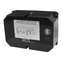
Mechanical design
· Plug-in design
· The built-in unit fuse protects the control contacts of burner control against
overloads
· Impact-proof plastic housing
· Able for optional mounting position at burner, on control panes or in control
cabinets
· Control unit driven by synchronous motor, the auxiliary relays, the electronic flame
signal amplifier as soon as all the rest of switch, control and adjustable elements
are build-on at stable PCBs and included in test circuit of burner control
· The burner control is secured to its base with 4 screws. The unit cover is protected
against tampering by means of 2 sealing screws (refer to «Dimensions»)
· Printed circuit board with electronic components
· Large connection area
· Made of black, impact-proof and heat-resistant plastic
· Lockout reset button with viewing window, for the lockout warning lamp
· Transparent viewing window for the program sequence indicator
- coupled to the program shaft
- uses easy-to-remember symbols to indicate the type of fault and the point in
time lockout occurred
· 4 extra terminals for the earth conductor, 4 extra terminals for the neutral
conductor, and 4 auxiliary terminals
LFE1...
Housing
 Loading...


