8/8 CC1N7781E June 01, 1999 Landis & Staefa Division
Dimensions in mm
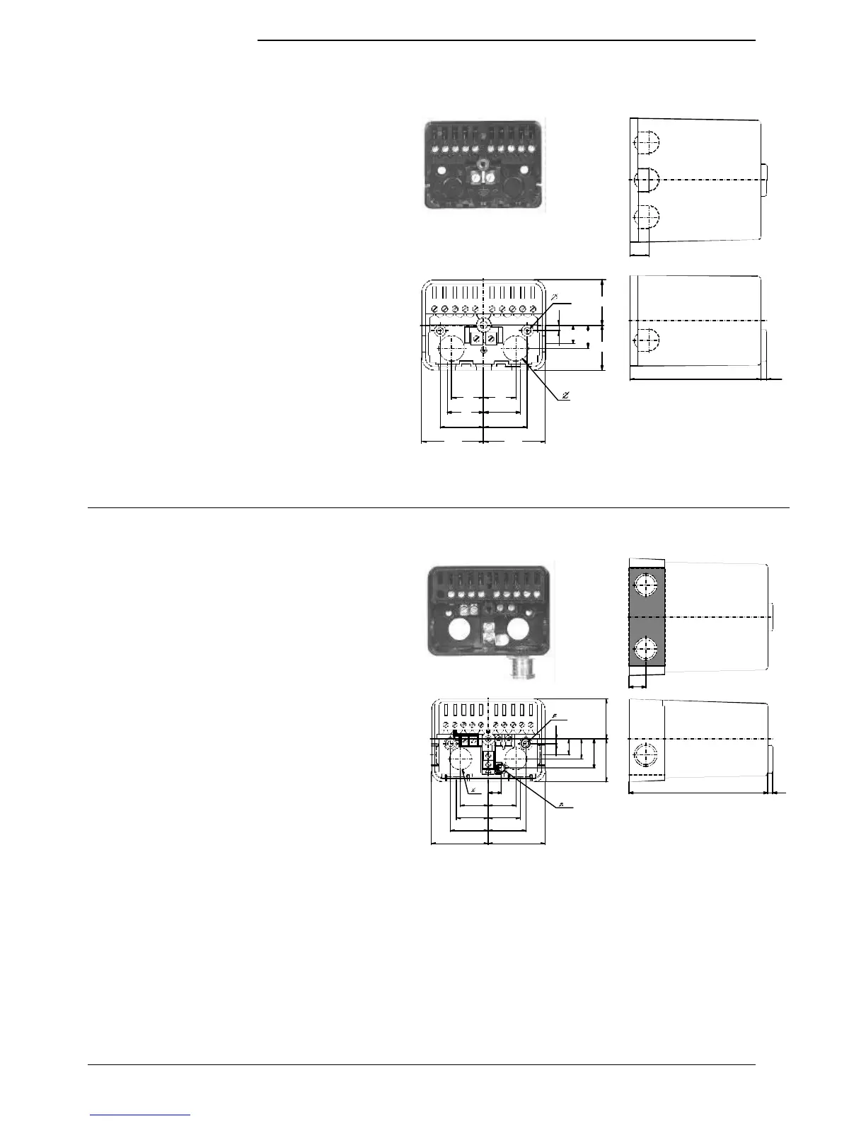
Dimensions
Base versions
16,2
4,6
90 4
13
12 345 678 910
12 345 678910
7781m02/1198
22
25
30
42,5
22
25
30
42,5
4
13
16
31
31
Low plug-in base, AGK 4 104 1345 0
Design features:
Ten-pole (screw terminals), with additional earth terminals.
Cable entry either through the bottom of the base
(two knock-out holes), the front, from the right or left side
(total of five cable entries).
High plug-in base, AGK 4 104 9025 0
with removable front
(shaded area in the drawing)
Design features:
Ten-pole (screw terminals):
and
- two auxiliary terminals with markings 11 and 12
- two neutral terminals, wired to terminal 2 (neutral input)
- two earth terminals, with earthing lug for the burner
For cable entry:
two cable entries in the bottom of the base and four threaded knock-
out holes for cable glands Pg11, one on the right, one on the left,
and in the removable front.
High plug-in base, AGK 4 104 9169 0
Features as above, but without the removable front (shaded area in
the drawing is open).
Front, AGK 4 104 9112 0
As a separate item, suited for use with plug-in base AGK 4 104 9169
0 (can also be used with AGK 4 104 9025 0, shaded area in the
drawing).
22
25
30
45
10 , 5
22
25
30
45
4
13
16
23,5
34
31,5
4,5
4,5
16
N
11 12
12
34
56
78
9 10
13
11 0 4
77 81m0 1/1198
1998 Landis & Staefa Produktion GmbH