11/25
Building Technologies CC1N7101en
HVAC Products 27.11.2008
Technical data (cont´d)
Mains voltage AC 230 V +10% / -15%
Mains frequency
50...60Hz ±6%
Perm. cable length from QRA... to
AGQ3…A27 (lay separate cable)
Max. 20m
Perm. cable length from AGQ3...A27 to
LME...A2
Max. 2m
Weight of AGQ3...A27 Approx. 140g
Perm. mounting position Optional
Degree of protection IP40, to be ensured through mounting
Power consumption 4.5VA
At mains voltage U
N
AC 220 V AC 240 V
Detector voltage at QRA... (with no load)
Terminal 3 off (refer to control sequence) DC 400 V DC 400 V
Terminal 3 on (refer to control sequence) DC 300 V DC 300 V
Detector voltage
Load by DC measuring instrument Ri > 10MΩ
Terminal 3 off (refer to control sequence) DC 380 V DC 380 V
Terminal 3 on (refer to control sequence) DC 280 V DC 280 V
DC current detector signals with UV detector
QRA...
Min. required Max. possible
Measurement at the UV detector QRA… 200µA 500µA
In connection with LME…A2 burner controls, use of UV ancillary unit AGQ3...A27 is
mandatory.
(A) Correct functioning of aged UV cells can be checked as UV test with a higher
supply voltage across the UV cell after controlled shutdown until terminal 3 on.
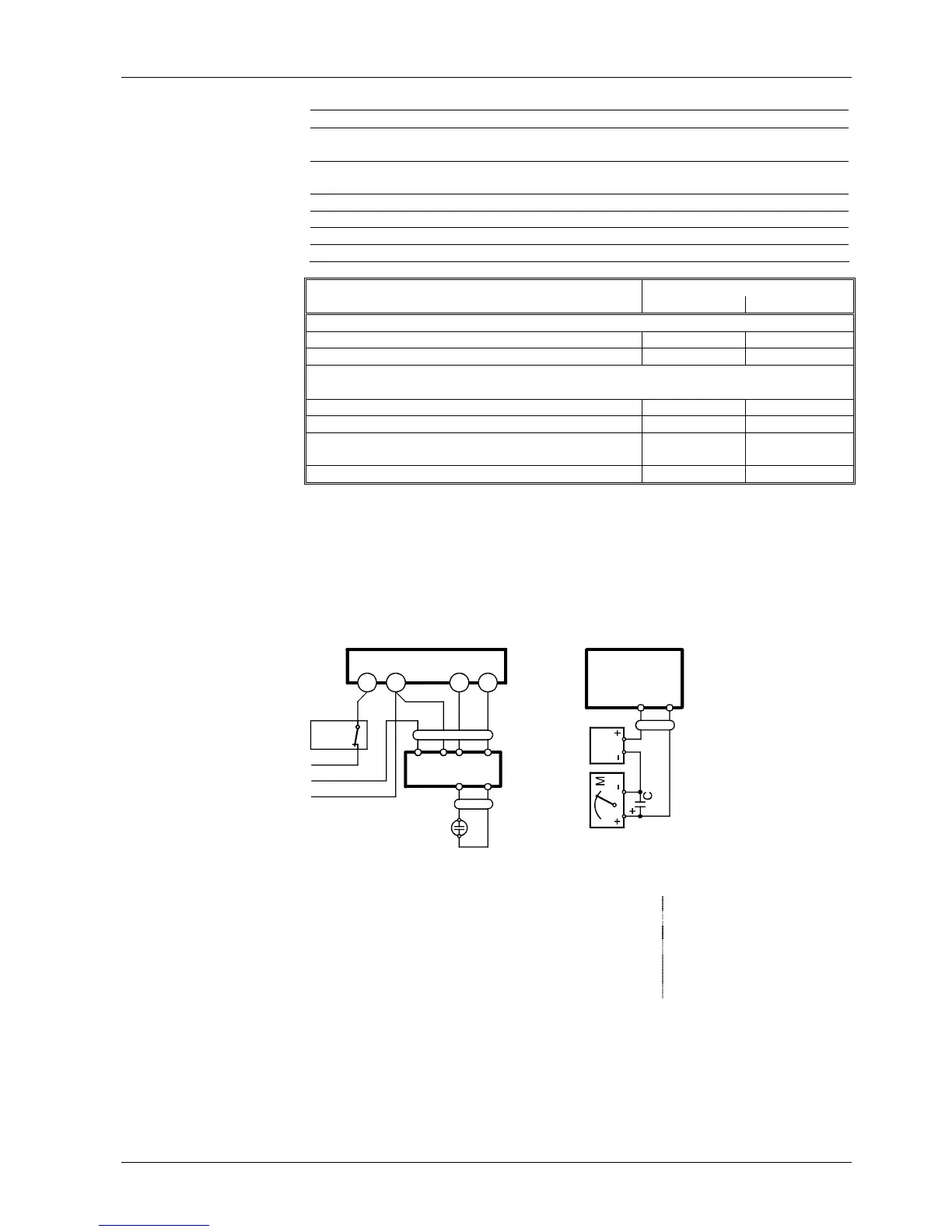
Connection diagram Measuring circuit for measuring the UV
detector current
12
2
3
1
7101a06/1107
GP/SB
R/W
L
L
N
QRA...
+
-
br
bl
rt
sw
AGQ3...A27
sw
bl
(A)
LME...A2
br
bl
rt
sw
AGQ3...A27
sw
bl
QRA
7101a07/1107
Measurement made at the UV detector
QRA…
C Electrolytic capacitor 100...470µF; DC 10...25 V bl Blue
M Microammeter Ri max. 5,000Ω br Brown
QRA... Flame detector gr Grey
GP Gas pressure switch rt Red
SB Safety limit thermostat sw Black
R Control thermostat or pressurestat
W Limit thermostat or pressure switch
Flame supervision
with AGQ3…A27 and
UV detector QRA...
 Loading...