Do you have a question about the Siemens LMV5 and is the answer not in the manual?
Introduces the LMV5 BMS, its functionalities, and applications.
Crucial safety precautions for operating and handling the LMV5 system.
Instructions for mounting the LMV5 base unit inside an enclosure, including screw specifications.
Procedure for mounting the AZL5 display through an enclosure face.
Guidelines for mounting SQM4x actuators to valves or dampers.
Overview of LMV5 wiring, terminal types, and numbering schemes.
Explains grounding types, CANBus system, and wiring requirements.
Wiring configurations for the load controller and its associated components.
Overview of LMV5 parameters, access levels, and parameter access via AZL5.
Procedure for addressing SQM4 actuators and setting their rotation direction.
How to define points for actuators and VSD across the firing range.
Functionality to protect against thermal shock during cold starts.
Troubleshooting common CANBus wiring and grounding problems.
Diagnosing issues with O2 sensors and VSD operation.
Lists common error codes, their meanings, and corrective actions.
Explains the LMV52's O2 trim functionality and its regulation process.
Detailed steps for commissioning and activating the O2 trim system.
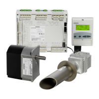
Information on the O2 trim system components and their specifications.
Introduces VSD control, VFDs, and AC induction motors used with LMV52.
Outlines the procedure for setting up and commissioning VSD control.
Covers Modbus master-slave, data transmission modes, and structure.
Lists supported Modbus functions and a table of addresses.
Explains Modbus settings and menu navigation within the AZL5.
Step-by-step guide for installing the ACS 450 software on a PC.
Procedures for saving, uploading, and updating parameter sets and AZL5 software.
How to create start-up reports and view system trends using ACS450.
Lists electrical, environmental, and output ratings for the LMV5 base unit.
Details specifications for AZL5 display and SQM4 actuators.
Specifications for flame scanners and various temperature/pressure sensors.
| Type | Burner Management System |
|---|---|
| Control System | Microprocessor-based |
| Application | Industrial burners |
| Fuel | Gas, oil, or dual fuel |
| Frequency | 50/60 Hz |
| Safety Standard | EN 298, EN 230 |
| Communication | Modbus |