Do you have a question about the Siemens LMV5 Series and is the answer not in the manual?
Details on the intended use of the LMV5... system for forced draft burners.
Essential safety warnings for operating and handling the LMV5... system.
Dimensional drawings and mounting recommendations for the LMV5... unit.
Dimensional drawings and mounting recommendations for the AZL5... unit.
Guidelines for installing the system and routing cables correctly.
Guidelines for connecting flame detectors for optimal signal transmission.
List of relevant technical standards and product certifications.
List of related documents and manuals for further information.
Information on fuse replacement, designed lifetime, and disposal.
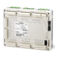
Overview of components integrated into the LMV5... basic unit.
Description of system operation, programming via AZL5..., and diagnostics.
Comparison table of LMV5... types and their features/certifications.
Details on transformer, mains frequency, power consumption, and safety class.
Specifications for input currents, voltages, and contact recommendations.
Load ratings for fan contactor, alarm output, ignition transformer, and valves.
Maximum cable lengths, types, and required cross-sectional areas.
List of fuses used in the LMV5... basic unit with their specifications.
Technical data for the AZL5... unit, including power and protection.
Technical data for the PLL52... module, including power and cable types.
Details on QRI detector operation, voltages, and cable length.
Information on ionization probe installation and detector current.
Specifications for QRA flame detectors used with AGQ1...A27 for intermittent operation.
Wiring diagram and terminal assignment for AGQ1...A27 with LMV5... and QRA detectors.
Data for QRA7... detector, including power supply and signal voltage.
Wiring diagram showing connections between QRA7... and LMV5... terminals.
Details on QRB... detector operation, currents, and cable length.
Notes on flame indication via AZL5... and handling extraneous light.
Environmental conditions for storage, transport, and operation of LMV5... system components.
Diagram and description of a typical installation with CAN bus and transformers.
Diagram for a setup with transformers for control panel and actuators.
Chart to determine maximum CAN bus cable lengths based on cable type and actuators.
Chart for determining maximum cable lengths with SQM45..., SQM48..., and SQM9... actuators.
Visual representation of AGG5.641 and AGG5.631 CAN bus cable types.
Details on CAN, RS-232 interfaces for PC and building automation.
Description of the VSD module for fan speed control and its basic diagram.
Methods for acquiring motor speed and direction of rotation.
Specifications for fuel meter sensors, frequency, and input configuration.
Information on VSD functional tests and EMC considerations.
Description of LMV52... features including O2 trim control and QGO20... sensor.
Settings for O2 trim controller/monitor activation and deactivation.
Alert for high flue gas temperatures indicating potential boiler issues.
Diagram showing terminal assignments for inputs and outputs of the LMV5... unit.
Diagram illustrating fuel valve and selection connections for gas and oil.
Terminal assignments for flame detectors (QRI, QRB, ION, QRA) with LMV5...
Diagrams for temperature and pressure sensor inputs and setpoint configurations.
Diagrams for load output and connections to SQM actuators via AZL5...
Terminal assignments for the VSD module, including speed sensor and fuel meter.
Terminal markings for temperature sensors connected to the PLL52... O2 module.
Terminal markings for QGO20... sensor and AZL5... interface connections.
Diagrams for direct gas ignition, gas pilot ignition 1, and gas pilot ignition 2.
Fuel valve control sequences for different gas burner configurations.
Diagrams for 1-stage, 2-stage, and 3-stage light oil burners.
Diagrams for modulating light oil burners with and without shutdown.
Fuel valve control sequence for light oil direct transformer ignition.
Diagrams for multistage heavy oil burners and associated notes.
Diagrams for modulating heavy oil burners and operational notes.
Fuel valve control sequence for heavy oil direct transformer ignition.
Diagrams for dual-fuel gas/light oil burners with gas pilot ignition.
Fuel valve control sequence for light oil with gas pilot ignition.
Diagrams for dual-fuel gas/heavy oil burners with gas pilot ignition.
Fuel valve control sequence for heavy oil with gas pilot ignition.
Detailed dimensional drawings of the LMV5... unit from multiple views.
Detailed dimensional drawings of the AZL5... unit from multiple views.
Dimensional drawings for PLL52... and AGG5.210/AGG5.220 modules.
| Brand | Siemens |
|---|---|
| Model | LMV5 Series |
| Category | Control Systems |
| Language | English |


 Loading...