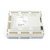
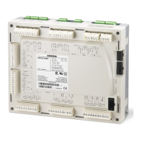
Do you have a question about the Siemens LMV52.440B1 and is the answer not in the manual?
General warnings and safety precautions for using the LMV5 unit.
Guidelines for proper installation and mounting of the LMV5 unit.
Electrical installation requirements and safety regulations for the LMV5.
Overview of provided connection facilities for flame detection.
Definition and implementation of safety time for fuel-air ratio control.
How the LMV5 can operate with internal, external, or BACS load controllers.
How the load controller operates in modulating or multistage modes.
Safety-related function to limit temperature, working like a 2-position controller.
Navigating the AZL5 menu structure for displays and settings.
How to perform standard parameterizations, including password entry.
Process for addressing actuators and defining their function assignment.
Parameterizing fuel-air ratio control curves for gas and oil.
Steps for adapting PID parameters using the self-setting function.
Initial steps for basic configuration, including burner identification.
Step-by-step guide for setting the fuel-air ratio control system for gas firing.
Configuration steps for multistage oil-fired operation.
Steps to configure the load controller, including selecting operating modes and sensors.
Defining control parameters for the load controller via standard sets or manual/automatic adaption.
Setting the integrated temperature limiter and its parameters.
Setting up cold start thermal shock protection parameters.
Information on powering the LMV5 unit using external transformers.
Steps for configuring the VSD according to the connected motor type.
How to configure the speed sensor and parameterize the number of protrusions.
Automatic measurement function for standardizing VSD speed.
How the O2 trim control system reduces combustion air based on control deviation.
How precontrol calculates air rate reduction based on learned burner behavior.
Operating modes for O2 trim control and O2 alarm functions.
Using the O2 alarm with or without O2 trim control for minimum and maximum O2 values.
Module for residual oxygen control, connected to LMV52 via CAN bus.
Configuring sensors connected to AZL5, including O2, air, and flue gas temperature sensors.
System configuration including actuators, VSDs, and fuel type parameterization.
Steps for commissioning the O2 trim control system, including setting fuel-air ratio and O2 alarm.
Setting fuel-air ratio control with FGR, including modes and actuator settings.
| Brand | Siemens |
|---|---|
| Model | LMV52.440B1 |
| Category | Control Systems |
| Language | English |


 Loading...