Do you have a question about the Siemens MJ-4A and is the answer not in the manual?
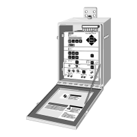
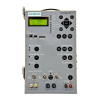
Diagram showing the physical arrangement of controls and indicators on the front panel.
Status lights and alphanumeric screen for displaying operational information.
Warning about death/injury from high voltage/moving parts.
Defines qualifications for personnel performing maintenance.
Explains the manual's purpose, scope, and structure.
Overview of standard panel features like display, metering, data logging.
Presents operational data and maintains historical data for analysis.
Details Voltage Limit and Reduction Controls.
Explains reverse power flow detection and modes.
Details mounting on various regulators and LTCs.
Supports comms and external control via terminals.
Describes indicators, display screen, and data access keys.
How to view data via menu or fast-path keys.
Keys for navigating menus and changing setpoints/data.
Shortcuts to frequently used data items for quick access.
Procedure for modifying data items using Change, Scroll, and Save keys.
Using fast-path keys for data item access and modification.
Explains status indicators like Alert, RPF, Band, Raise/Lower.
Explains U2 P2, Neutralite Test, Drag Hands Reset, Quick Key, Remote/Local, Auto/Manual keys.
Explains power switch positions and Auto/Manual switches/buttons.
Required switch settings before bypassing the regulator.
Details external source/calibration posts and fuses.
Schematic of power and motor control terminal connections.
Setting up the data port for PC or communications device connection.
Methods to view data via menu selection or fast-path keys.
How MJ-4 Control Panel information is organized into menus.
Procedure for modifying configuration and alphanumeric settings.
Using fast-path keys as shortcuts for data item access.
Steps for customizing the control panel to environment and needs.
Defines regulator and power distribution system configuration.
Details the purpose of key configuration menus.
Shows typical Siemens regulator nameplates for configuration.
Details configuration parameters for regulator identification.
Details parameters for voltage and current transformer ratios.
Details parameters for load current, power flow modes, and basis voltage.
Details parameters for meter voltage and current thresholds.
Details parameters for neutral overrun, meter scaling, and current threshold.
Details parameters for setting time, date, and demand calculation methods.
Details parameters for screen timeouts and automatic variamp settings.
Setting up Event and Interval Logs for status recording.
How interval logging occurs and data captured.
Overview of password protection system for data access.
Procedures for entering, changing, and enabling/disabling passwords.
Setting up Local Data Port parameters like baud rate and parity.
Details configuration items for the communications module.
Accesses status and operations of tap changer contacts.
Accesses hardware configuration and internal test items.
Procedures for entering and changing the System Key.
How to change Level 1 and Level 2 passwords.
Steps to enter passwords for access or to change them.
Accesses status and operations of tap changer contacts.
Accesses hardware configuration and internal test items.
Customizing the Quick List for fast access to menu items.
Defines 'Source' and 'Load' based on power flow and regulator type.
How to view operating values like voltage, current, and power.
Lists and defines data items available in the <METER> Menu.
Explains how Power Factor and KVA data are derived and displayed.
Explains Forward/Reverse Real (kWhr) and Reactive (kVARhr) energy values.
How the MJ-4 records meter data upon specific events.
How to quickly navigate and view individual events in the log.
How the MJ-4 records data at predefined time intervals.
Records tap changer stepping operations and related data.
How the MJ-4 tracks tap position using a 'dead reckoning' procedure.
How alerts represent exception conditions and are stored.
How to view alert conditions and acknowledge them.
How to view calculated harmonics data for voltage and current.
Indicates the present level of Voltage Reduction Control (VRC).
Summary of the four operating modes: Manual, Off, Auto-Remote, Auto-Local.
How the automatic control algorithm maintains output voltage within limits.
How the control program monitors and scales output voltage.
How VLC monitors output voltage and inhibits tap changes.
How the MJ-4 senses and adjusts for power flow reversals.
How the MJ-4 alternates between forward and reverse modes.
Explains the six supported power flow modes.
Tap changes inhibited under reverse power flow.
Tap changes inhibited under forward power flow.
Tap changer operates for forward/reverse flow above I Threshold %.
Regulator idles at last tap position during abnormal reverse flow.
Regulator returns to neutral position during abnormal reverse flow.
Handles power flow from consumer to utility with specific LDC values.
Using MJXplorer for configuration, data transfer, and software updates.
Using MJXtra application to upload new software versions.
Outlines basic field procedures for diagnosing and repairing faults.
Steps for visually inspecting the unit and its connections.
Using alert messages to diagnose system and internal MJ-4 problems.
Procedures for checking and recalibrating voltage and current inputs.
Details calibration procedures for U2, P2 voltage, and load current.
How the unit performs internal diagnostics and checksum tests.
Specifies operating temperature, humidity, voltage, and frequency ranges.
Details metering accuracy and electrical transient immunity.
Recommended switch settings and PDS interface details.
Guidance for replacing previous control panel models.
Procedure for replacing an already installed MJ-4 panel.
Advises against field maintenance, recommending authorized facilities.
Provides a typical schematic diagram for reference.
Details lead designations and terminal block connections.
Schematic diagram for ANSI Type 'B' (Inverted) regulator.
Steps to determine leading/lagging regulators in Delta configurations.
How to determine and set Line Drop Compensation values.
Mandatory steps to disable the control panel before bypassing.
Mounting and installation of Fiber Optic and RS-232/485 modules.
Quick reference for navigating menus and using fast-path keys.
Shows external connections for the MJ terminal strip.
Locations and descriptions of MJ-4 jumpers and battery.
Procedures for replacing the MJ-4 battery and data backup.
Details pinout and signal descriptions for P2A.
Diagram showing jumper locations and data port settings.
Detailed steps for replacing the MJ-4 battery.
Details pinout and signal descriptions for P2A.
Details pinout and signal descriptions for P3B.
Procedure to view the current load voltage value.
How to view and reset maximum/minimum meter or tap values.
Procedure to view and set the forward voltage level setpoint.
Procedure to view and set the bandwidth setpoint.
Procedure to view and set the time delay setpoint.
How to view and set resistance and reactance compensation values.
How to view total operations and other counter data.
Steps to configure panel settings via menus.
How to calibrate U2/P2 voltage inputs using a voltmeter.
| Brand | Siemens |
|---|---|
| Model | MJ-4A |
| Category | Control Panel |
| Language | English |


 Loading...