31 / 60
Siemens Actuators SAS.., SAT.. for valves CE1P4041en
Smart Infrastructure Functions and control 2019-04-09
4.2 Modulating control
The modulating positioning signal
drives the actuator steplessly. The
positioning signal range
(DC 0...10 V / DC 4...20 mA /
0...1000 Ω) corresponds in a linear
manner to the positioning range (fully
closed...fully open, or 0…100 %
stroke).
The actuator is controlled via terminal
Y or forced control Z (page 35). The
desired stroke is transferred to the
valve stem.
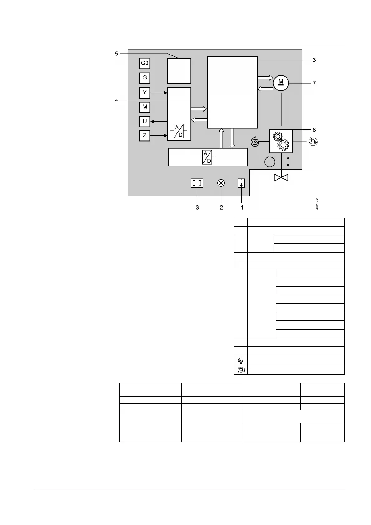
1 Calibration slot
2 LED (2 colors)
3
DIL
switches
Changeover of characteristic
Positioning signal
4 A/D conversion
5 Power supply
6
Control
functions
Identification of seat
Position control
Motor control
Detection of foreign bodies
Calibration
Forced control
Characteristics function
Manual adjustment
7 Brushless DC motor
8 Gear train
Fail safe function
Manual adjuster
Positioning signal Stroke actuator
Control path valve
AàAB
Bypass valve
B à AB
Signal Y, Z increasing Actuator’s stem extends Opening Closing
Signal Y, Z decreasing Actuator’s stem retracts Closing Opening
Signal Y, Z constant
Actuator’s stem
maintains the position
Maintains the position
No voltage at Y1 and
Y2; with fail safe
function
Actuator’s stem retracts Closing Opening
Observe the information given in chapter 4.2.1 Positioning signal and flow
characteristic selection on page 31.
Note

 Loading...