MT Series SSC Electronic Valve Actuator, 24 Vac Floating Control Technical Instructions
Document Number 155-314P25
May 10, 2011
Siemens Industry, Inc. Page 3
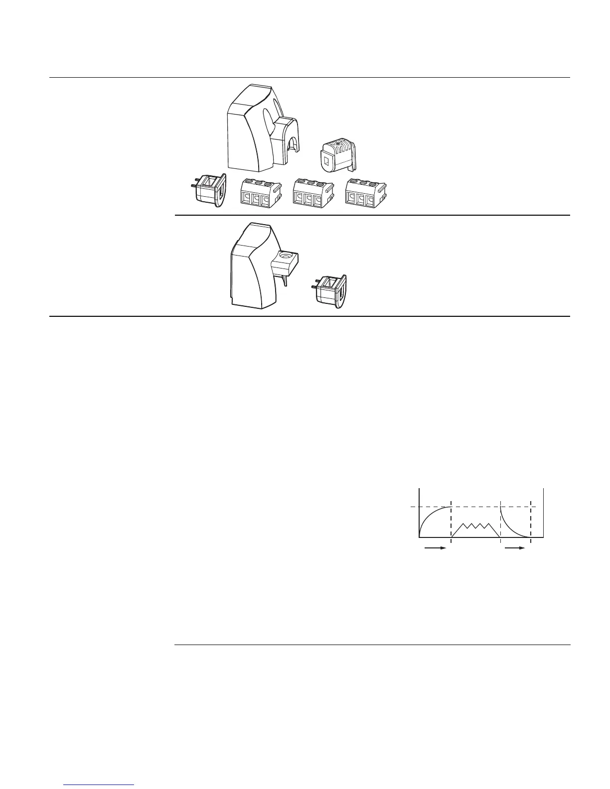
Service Kits
EA1156R1
EA1162R1
EA0851R1
EA1138R1
EA1138R1
EA1138R1
411555648 For actuators with date
codes of 031215F or later.
Kit contains:
- Terminal cover
- Cover screws-2 (not shown)
- Tailpiece
- Tailpiece screw-1 (not shown)
- Cable lock
- Terminal block-3
EA0850R1
EA0851R1
411656088 For actuators with date
codes before 031215F.
Kit contains:
- Terminal Cover
- Cable lock
- Cover screw- 1 (not shown)
Operation
A 24 Vac control signal to terminal Y1 extends the actuator shaft proportionately to the
length of time the signal is applied.
A 24 Vac control signal to terminal Y2 retracts the actuator shaft proportionately to the
length of time the signal is applied.
In the event of a power failure with no control voltage, the non-spring return SSC81U
will hold its last position.
In the event of a power failure, the SSC81.5U returns to the stem up 0 position. The
SSC81.5U includes an electronic return mechanism that functions as follows. See
Figure 1.
• At power-up (t
0
), a capacitor must
charge to its maximum capacity
(Max, t
c
). This will take a maximum
of 180 sec, during which time no
actuator movement occurs.
• Once the capacitor is fully charged
(t
c
), normal actuator operation
occurs.
• If a subsequent power failure occurs
(tn) of greater than 5 seconds, the
capacitor discharges (t
d
) and the
actuator spring returns to stem up 0
position.
EA0798R2
TIME
MAX
180s.
MAX
30s.
CHARGE
Max
0
NORMAL
ACTUATOR
OPERATION
ACTUATOR
POSITION
TIME TO
DISCHARGE
TIME TO
CHARGE
t
0
t
c
t
n
t
d
Figure 1. SSC81.5U Electronic Spring
Return Mechanism.

 Loading...


