MT Series SSC Electronic Valve Actuator, 24 Vac Floating Control Technical Instructions
Document Number 155-314P25
May 10, 2011
Siemens Industry, Inc. Page 5
Wiring
Use earth ground isolating, step-down Class 2 transformers. Do not use
autotransformers.
Determine supply transformer rating by summing total VA of all actuators used. The
maximum rating for a Class 2 step-down transformer is 100 VA.
Do not power more than 10 actuators by one transformer. (Use 0.5 amp fuse on
secondary actuator.)
NOTE: Can be wired either neutral or hot switched.
CAUTION:
Terminals must be properly wired for correct function and full life of the
actuator.
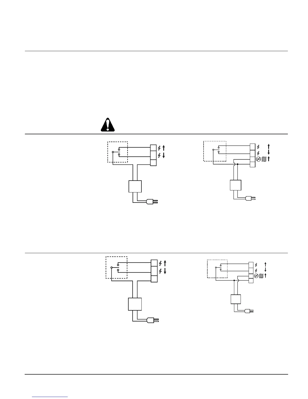
Wiring Diagrams
NEUT
CONTROLLER
ACTUATOR
EARTH GROUND
ISOLATING CLASS 2
TRANSFORMER FOR
24 Vac POWER
120 Vac
1
0
Y2
Y1
G
24
Vac
EA0795R1
Figure 4. SSC81U Neutral Switching
Non-Spring Return.
EA1234R1
NEUT
CONTROLLER
EARTH GROUND
ISOLATING CLASS 2
24 Vac TRANSFORMER
120 Vac
24 Vac
ACTUATOR
G
Y2
Y1
G0
1
0
0
Figure 5. SSC81.5U Neutral Switching
Spring Return.
Y2 Retracts actuator shaft
Y1 Extends actuator shaft
G System potential (hot)
G0 Neutral – (SSC81.5U Only)
NEUT
EARTH GROUND
ISOLATING CLASS 2
TRANSFORMER FOR
24 Vac POWER
120 Vac
1
0
Y2
Y1
G
24
Vac
EA0585R1
Figure 6. SSC81U Hot Switching
Non-Spring Return.
EA1235R1
NEUT
CONTROLLER
EARTH GROUND
ISOLATING CLASS 2
24 Vac TRANSFORMER
120 Vac
24 Vac
ACTUATOR
G
Y2
Y1
G0
1
0
0
Figure 7. SSC81.5U Hot Switching
Spring Return.
Y2 Retracts actuator shaft
Y1 Extends actuator shaft
G Neutral
G0 System potential (hot) -SSC81.5U Only

 Loading...


